Ultrasonic probe, and photoacoustic-ultrasonic system and inspection object imaging apparatus including the ultrasonic probe

a technology of ultrasonic imaging and photoacoustic wave, which is applied in the direction of tomography, instruments, diagnostic recording/measuring, etc., can solve the problems of affecting fibers, deteriorating spatial resolution of ultrasonic images, and sensitivity reduction

Inactive Publication Date: 2011-04-21
CANON KK
View PDF33 Cites 75 Cited by
  • Summary
  • Abstract
  • Description
  • Claims
  • Application Information

AI Technical Summary

Benefits of technology

An object of the present invention is to provide an ultrasonic probe capable of forming an image without degradation even when a frequency band of a photoacoustic wav...

Problems solved by technology

However, as described in Japanese Patent Application Laid-Open No. 2005-021380, when the common probe is used to receive the photoacoustic wave and the ultrasonic wave which have frequency bands different from each other, there arises a problem that spatial resolution is deteriorated in the ultrasonic image.
However, a signal contained in a harmonic component is attenuated more than a signal contained in a fundamental component, and hence there ...

Method used


Image

  • Ultrasonic probe, and photoacoustic-ultrasonic system and inspection object imaging apparatus including the ultrasonic probe
  • Ultrasonic probe, and photoacoustic-ultrasonic system and inspection object imaging apparatus including the ultrasonic probe
  • Ultrasonic probe, and photoacoustic-ultrasonic system and inspection object imaging apparatus including the ultrasonic probe

Examples


first embodiment

Ultrasonic Probe and Inspection Object Imaging Apparatus

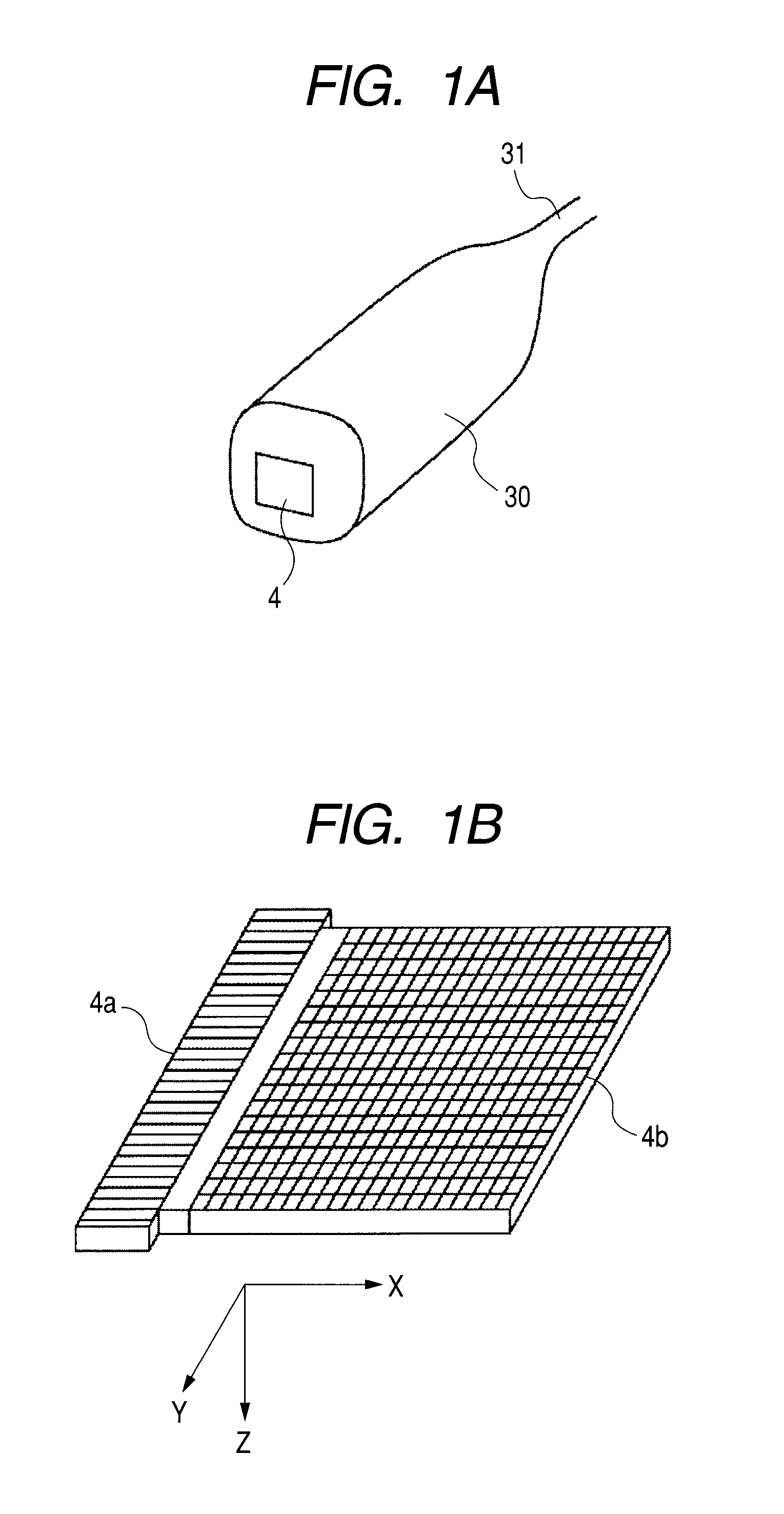
An ultrasonic probe according to this embodiment includes a first array device capable of transmitting and receiving an ultrasonic wave; and a second array device capable of receiving a photoacoustic wave. The first array device includes plural electromechanical transducers arranged in a first direction. The second array device includes plural electromechanical transducers arranged two-dimensionally. The first array device and the second array device are provided on the same plane and in a second direction. In the present invention, the “same plane” is not necessarily required to be strictly the same plane as long as the plane can be regarded as substantially the same plane. In the definition of “substantially the same plane”, it is acceptable that the plane on which the array devices are provided includes irregularities within a range of processing accuracy and includes inclination or level difference as long as the contact co...

second embodiment

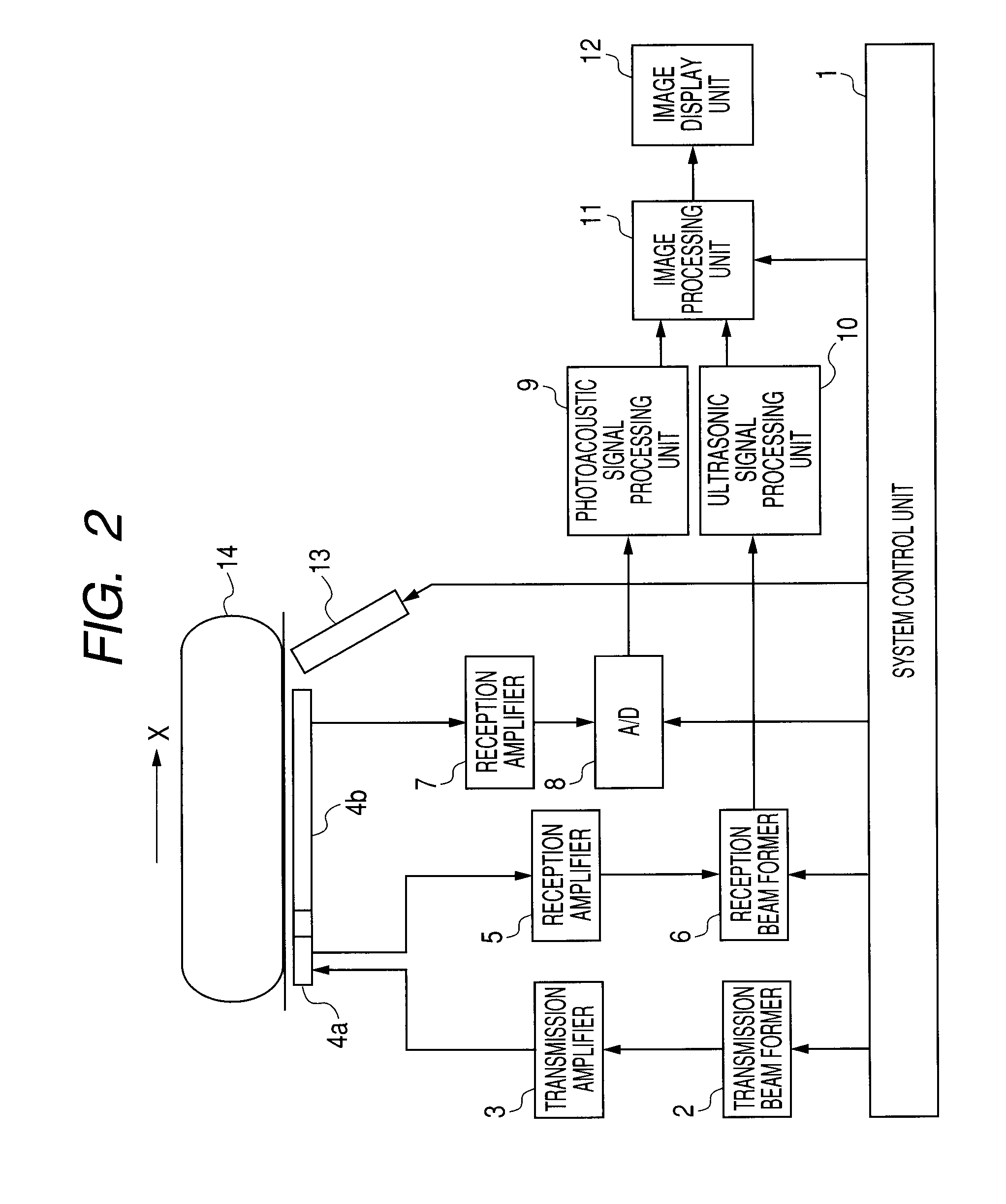
Photoacoustic-Ultrasonic System

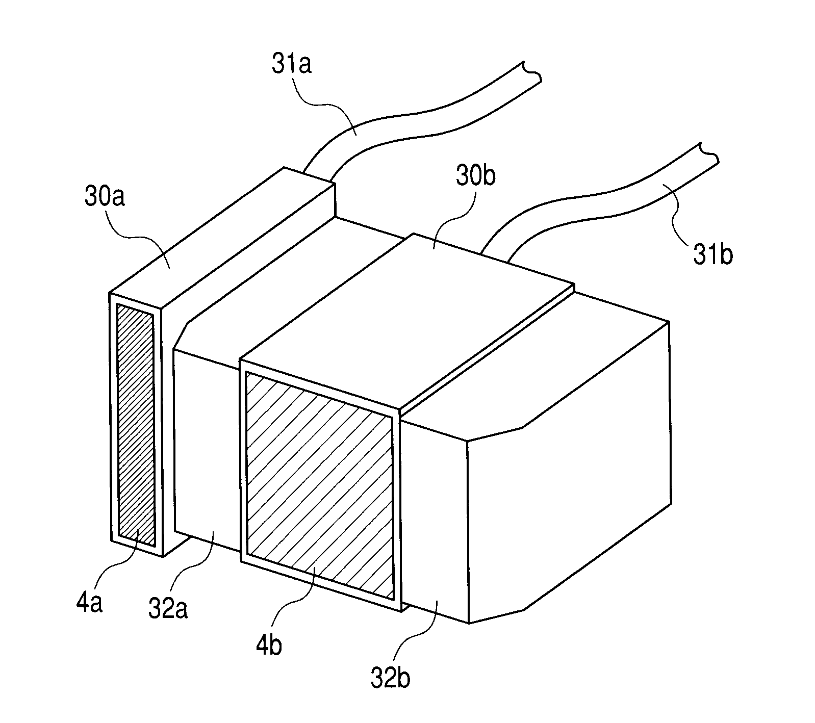
Next, a photoacoustic-ultrasonic system in which an optical system is combined with an ultrasonic probe is described. FIG. 7A is a perspective view illustrating the photoacoustic-ultrasonic system including the ultrasonic probe and the optical system according to this embodiment.

A first probe for transmitting and receiving an ultrasonic wave includes a probe case 30a, a cable 31a, and a transducer 4a. A second probe for receiving a photoacoustic wave includes a probe case 30b, a cable 31b, and a transducer 4b. The transducer 4a is a first array device capable of transmitting and receiving the ultrasonic wave. The transducer 4b is a second array device capable of receiving the photoacoustic wave. A one-dimensional (linear) array is employed for the ultrasonic transducer 4a while a two-dimensional array is employed for the photoacoustic transducer 4b.

An optical prism 32a is provided in an interspace between the ultrasonic transducer 4a and the photoacou...

example

Hereinafter, in this example, a case where the probe according to the present invention is used for a mammary examination is specifically described. In the mammary examination, it is sufficient that an ultrasonic signal and a photoacoustic signal for up to a depth of 4 cm are acquired. The probe used in this case is the probe of FIGS. 1A and 1B which is used in the description above.

A laser light intensity allowable to be applied to a human body is 100 mJ / cm2, and hence a range in which a sufficient photoacoustic signal can be acquired is 4 cm in depth and 4 cm in width. Accordingly, one side of a photoacoustic probe was set to 4 cm. Accordingly, one side of the photoacoustic probe was set to 4 cm. The device pitch was set to 2 mm in consideration of probe sensitivity and a frequency of 1 MHz to be used, whereby a two-dimensional array probe including 400 devices was formed. An electrostatic capacity type ultrasonic transducer having a band width of 130% was used as the two-dimensio...


PUM


Abstract

Provided are an ultrasonic probe capable of forming an image without degradation even when the frequency band of a photoacoustic wave and the frequency band of an ultrasonic wave used in ultrasonography are separated from each other, and an inspection object imaging apparatus including the ultrasonic probe. The ultrasonic probe includes a first array device capable of transmitting and receiving an ultrasonic wave; and a second array device capable of receiving a photoacoustic wave. The first array device includes plural electromechanical transducers arranged in a direction perpendicular to a scanning direction, the second array device includes plural electromechanical transducers arranged in a two-dimensional manner, and the first array device and the second array device are provided on the same plane and in the scanning direction.

Description

TECHNICAL FIELDThe present invention relates to an ultrasonic probe for transmitting and receiving an ultrasonic wave and for receiving a photoacoustic wave, and to a photoacoustic-ultrasonic system and an inspection object imaging apparatus including the ultrasonic probe.BACKGROUND ARTA conventional tomographic imaging apparatus which obtains a tomographic image using an ultrasonic wave includes: a probe for transmitting an ultrasonic wave to a sample and receiving the reflected ultrasonic wave; a transmitting portion for supplying an ultrasonic signal to the probe; a receiving portion for receiving the reflected wave; and a unit for converting the received reflected wave signal into a luminance signal for visualization. When a time-series tomographic image acquired by the apparatus is used, it is possible to observe an inside of a sample. In the apparatus according to one mode, a unit for performing scanning of a probe two-dimensionally scans a sample with an ultrasonic wave to ob...

Claims


Application Information

Patent Timeline
IPC IPC(8): G01N29/24G01N29/26
CPCA61B5/0095A61B8/0825A61B8/483A61B8/5238A61B8/14A61B5/0035A61B8/145A61B8/4416A61B8/4444A61B8/4494
Inventor SOMEDA, YASUHIROSAITO, KEISHIASAO, YASUFUMINAKAGAWA, KATSUMIICHIHARA, SHIGERU
Owner CANON KK
Why Eureka
Try Eureka