Support frame for solar energy device

a solar energy and support frame technology, applied in the direction of photovoltaic supports, heat collector mounting/supports, light and heating apparatus, etc., can solve the problems of insufficient structural strength, inability to meet the needs of support frames, and high manufacturing costs of aluminium alloy support frames, so as to improve the service life, and reduce the effect of cos

Inactive Publication Date: 2011-04-21
SHA XIAOLIN +1
View PDF15 Cites 13 Cited by
  • Summary
  • Abstract
  • Description
  • Claims
  • Application Information

AI Technical Summary

Benefits of technology

[0007]An object of the present invention is to provide a support frame for solar energy device, which has a lower cost, corrosion protection, long service life, higher structural strength, good normability, is capable of site pouring and adapted for any amount of solar energy devices.

Problems solved by technology

Obviously, it is unavoidable to need the support frame while installing and utilizing the above solar energy devices.
However, it needs additional devices, such as cement columns, while fixed on the ground.
In addition, the aluminium alloy support frame has a higher manufacture cost and insufficient structural strength.
As a result, once encountering strong wind, the aluminium alloy support frame is easy to be damaged, the service life is affected accordingly.
The angle iron support frame has a sufficient structural strength, but poor corrosion resistance, thus it is easy to be corroded and rusted while long-term exposed to outdoors, the sun and rain.
Accordingly, the service life of the angle iron support frame is affected.
In addition, the angle iron support frame is manufactured by cutting and welding and needs site welding so that the difficulty of installation is increased.
The former wastes materials, increases cost and has a bad stability, the latter needs redesigning for different amounts of solar energy devices and can't be common used, thus increases cost, and has a lower re-using rate.

Method used


Image

  • Support frame for solar energy device
  • Support frame for solar energy device
  • Support frame for solar energy device

Examples


Embodiment Construction

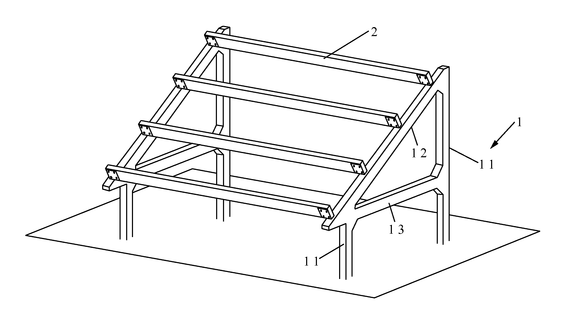
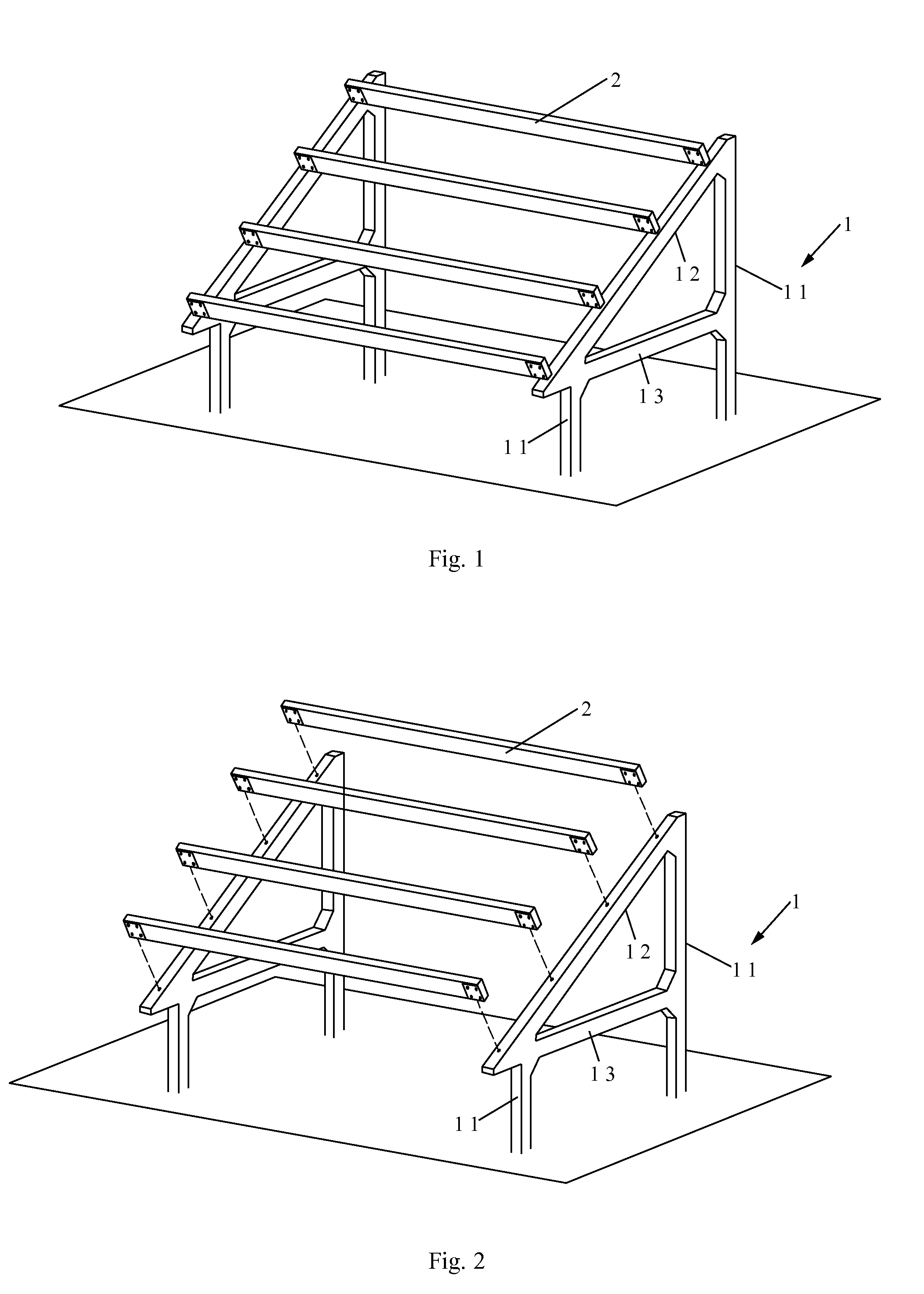
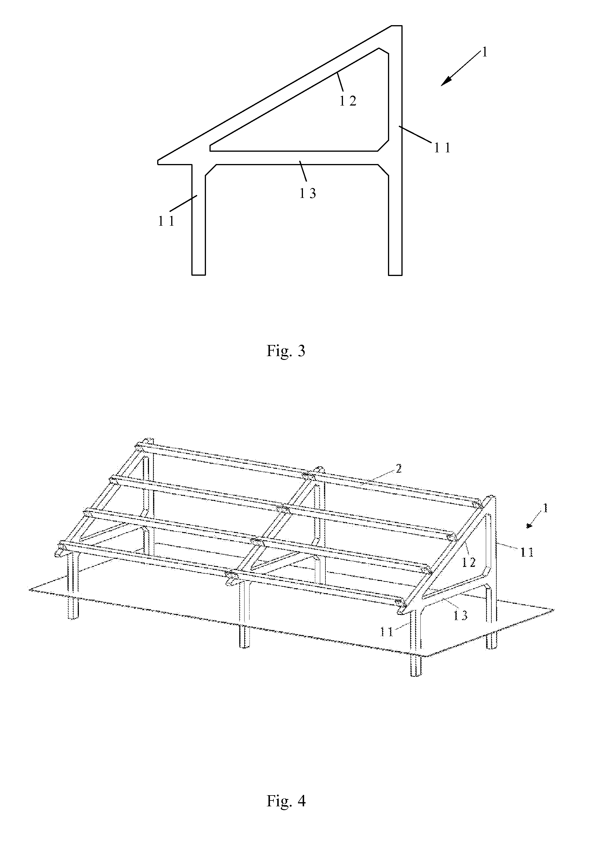
[0019]Referring to FIGS. 1 and 2 of the drawings, a support frame for solar energy device according to a preferred embodiment of the present invention is illustrated, in which the support frame comprises at least two support bodies 1, and at least two lintels 2, each of which being provided between the two support bodies 1 and forming a support plane to place a solar energy device, such as a solar panel, wherein each of the support bodies 1 and lintels 2 are made of reinforced concrete.

[0020]Because the elements of the support frame for solar energy device are made of reinforced concrete, the support frame is capable of site pouring and then assembling without worrying out the lack of some elements. In addition, according to specific requirements of construction site, the structure or size of the support frame for solar energy device can be adjusted appropriately to meet the requirement, so as to save the trouble of transportation and reduce the cost. For example, the number of the ...


PUM


Abstract

The present invention discloses a support frame for solar energy device, which includes at least two support bodies, and at least two lintels, each of which being provided between the two support bodies. Each of the support bodies and lintels is made of reinforced concrete. Each of the support bodies includes two supporting columns, and a transverse beam fixedly provided between two top ends of the two supporting columns respectively. Two ends of each of the lintels are fixedly provided on a transverse beam of one of the support bodies and a transverse beam of an adjacent support body, respectively. Each of the support bodies further includes a strengthened beam fixedly provided between the two supporting columns. The present invention has a lower cost, corrosion protection, long service life, higher structural strength, good normability, is capable of site pouring and adapted for any amount of solar energy devices.

Description

BACKGROUND OF THE PRESENT INVENTION[0001]1. Field of Invention[0002]The present invention relates to a support frame, and more particularly to a support frame for solar energy device.[0003]2. Description of Related Arts[0004]With the rapid development of social economy, the reserves of oil, coal and other non-renewable energy sources are getting fewer and fewer, and the price is getting higher and higher. Nowadays, solar energy as one of important clean energies is paid more and more attention and widely used, such as a flat-plate solar collector and a solar panel. Obviously, it is unavoidable to need the support frame while installing and utilizing the above solar energy devices.[0005]The currently common support frame for solar energy device is mainly made of aluminium alloy and angle iron. The aluminium alloy support frame has a light weight and is convenient for being transported. However, it needs additional devices, such as cement columns, while fixed on the ground. In additio...

Claims


Application Information

Patent Timeline
Patent Type & Authority Applications(United States)
IPC IPC(8): F24J2/52
CPCF24J2/5232F24J2/5237H02S20/00Y02E10/47Y02E10/50F24J2002/4687F24S25/11F24S25/12F24S2080/012H02S20/10
Inventor SHA, XIAOLINSHA, YAN
Owner SHA XIAOLIN
Why Eureka
Try Eureka