Aircraft joint

a technology for fuselage joints and aircraft, applied in the field of aircraft fuselage joints, to achieve the effect of easing assembly problems

Inactive Publication Date: 2011-04-21
AIRBUS OPERATIONS LTD
View PDF8 Cites 68 Cited by
  • Summary
  • Abstract
  • Description
  • Claims
  • Application Information

AI Technical Summary

Benefits of technology

[0018]To ease assembly issues arising from manufacturing tolerances at least some of the lugs may include eccentric bushes. These bushes may be rotated, where necessary, to align the lugs on each side of the joint prior to pinning. This would reduce or negate the requirement for drilling out of the lugs in the final assembly, which currently occupies a significant amount of the total time to form a wing-fuselage joint by conventional shear joints. It is envisaged that a wing-fuselage joint in accordance with this invention may be formed in around 10 hours.

Problems solved by technology

Furthermore, the attachment loads remain in-plane, making it weight competitive compared with tension joints.

Method used


Image

  • Aircraft joint
  • Aircraft joint
  • Aircraft joint

Examples


Embodiment Construction

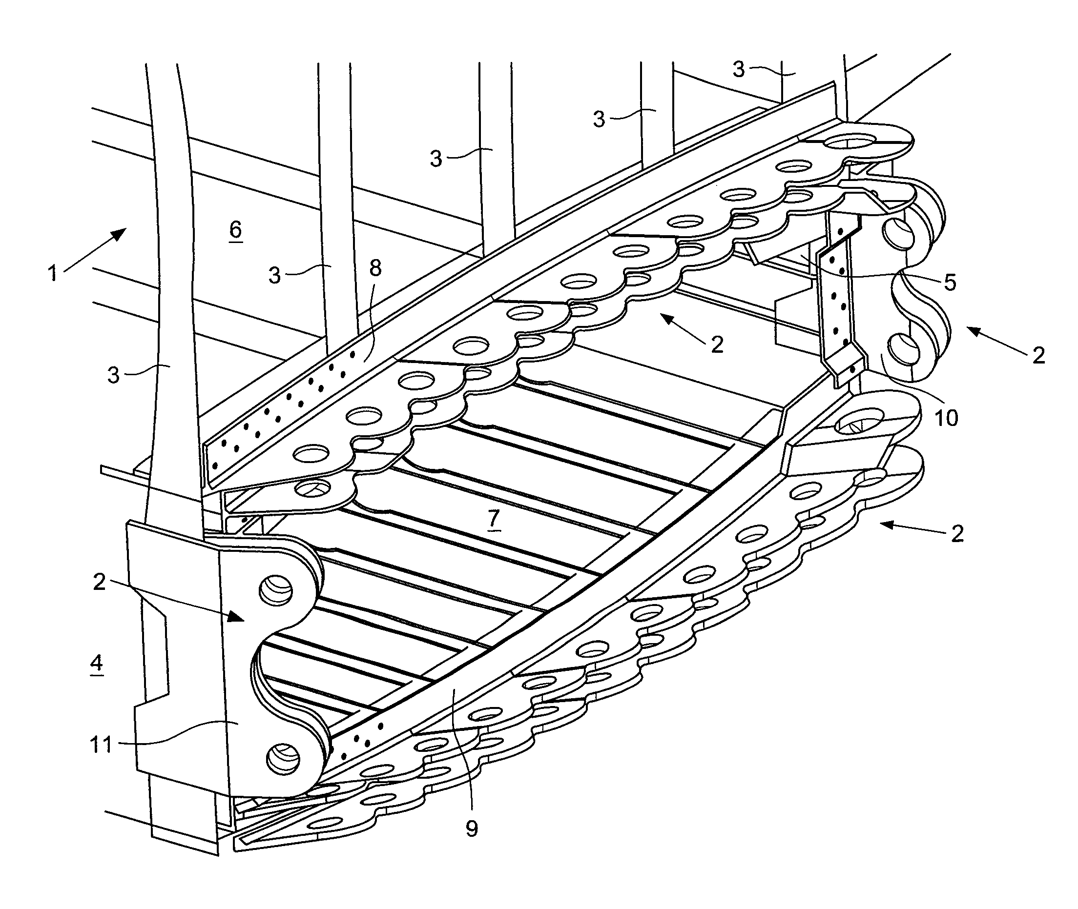
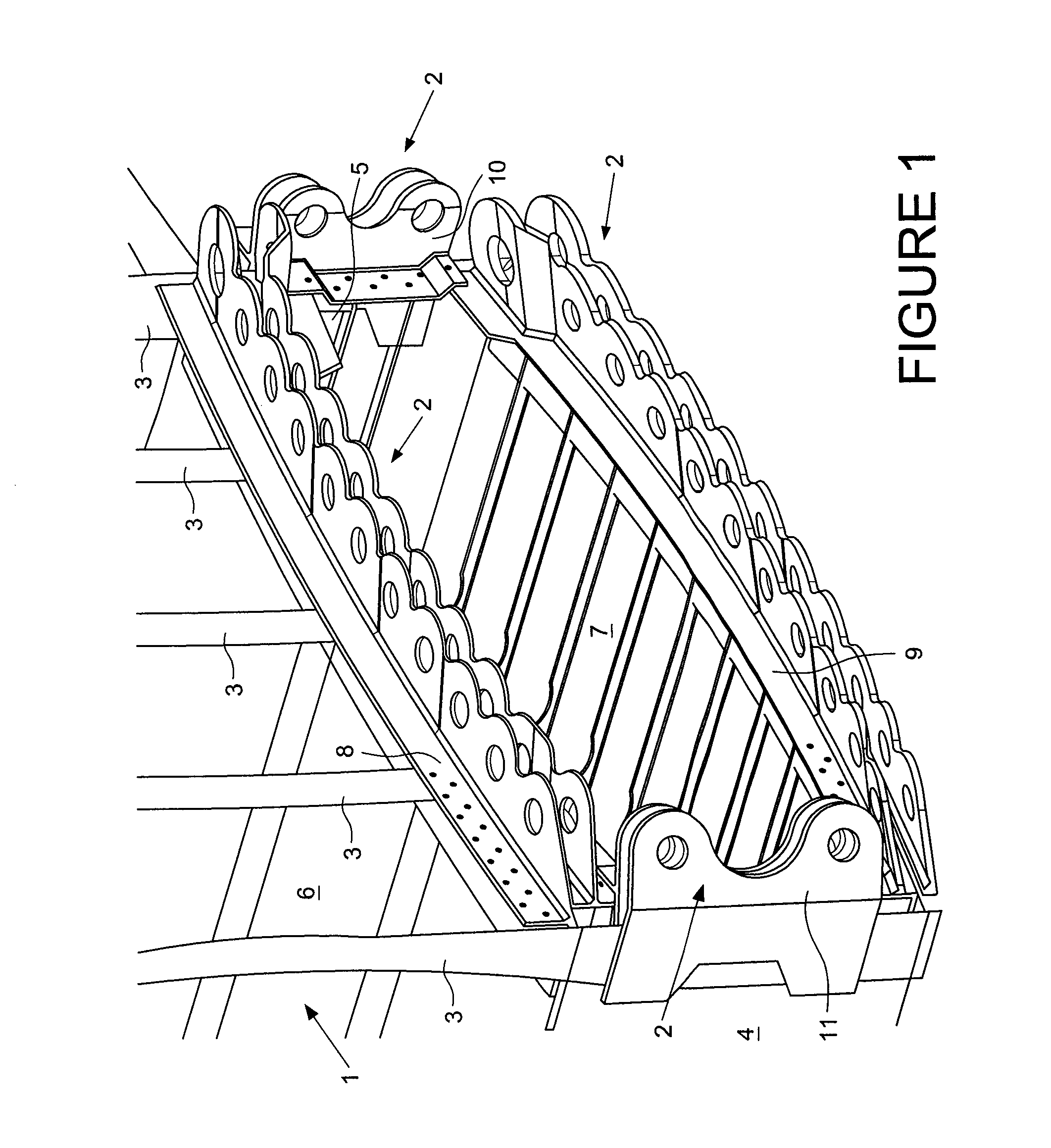
[0027]FIG. 1 shows a partial view of a centre wing box structure 1 having a series of double lugs 2 provided around the entire circumference of the centre wing box structure 1 prior to connection to an aircraft wing (not shown) to form a wing-fuselage joint. The centre wing box structure 1 is connected to fuselage structural frames 3 which run around the circumference of the fuselage. The centre wing box structure 1 comprises a front spar 4, a rear spar 5, an upper cover 6 and a lower cover 7. At each end of the centre wing box structure 1 there is provided a centre wing box rib 19 (not shown in FIG. 1 for clarity, but shown in FIGS. 5a, 5b and 6).

[0028]The upper double row of lugs is formed in an upper “cruciform” component 8 which is attached by its inboard flange to the centre wing box upper cover 6; by its upper flange to the fuselage structural frames 3; and by its lower flange to the centre wing box rib 19 (not shown in FIG. 1). The upper double row of lugs 2 is formed in firs...


PUM

PropertyMeasurementUnit
relative movementaaaaaaaaaa
circumferenceaaaaaaaaaa
tensionaaaaaaaaaa

Abstract

A method of joining a wing to an aircraft fuselage by forming a series of pinned lug joints between a fuselage side and a wing side of a wing box structure. The joint forming process includes providing a single row of lugs on one side of the joint to be formed, and providing a respective double row of lugs on the other side of the joint to be formed. A gap between opposing lugs of the double row varies along the row. The wing side and the fuselage side of the wing box structure are brought together such that the lugs of the single row are located within the respective gaps between opposing lugs of the double row, and the lugs are pinned to form the series of pinned lug joints. Also, a joint formed by the method.

Description

FIELD OF THE INVENTION[0001]The present invention relates to an aircraft wing-fuselage joint.BACKGROUND OF THE INVENTION[0002]Aircraft wing to fuselage joints need to be lightweight and low cost to produce and maintain. Increasingly in the current aircraft industry, the time to assemble such joints is also a key driver, as manufacturers face the challenge of greater production rates to meet demand. Specifically, the time to assemble large aircraft assemblies (e.g. wing to fuselage) is of financial interest, due to the large cost of the work in progress locking in cash to the business at the final assembly line.[0003]Most large aircraft have a two-spar wing box structure, and the wing-fuselage joint connects the centre wing box structure on the fuselage side to the wing box structure on the wing side. Of course, two such joints are provided, one on each side of the fuselage. The wing-fuselage joint typically comprises a series of joints around the circumference of the wing box struct...

Claims


Application Information

Patent Timeline
Patent Type & Authority Applications(United States)
IPC IPC(8): B64C1/26B23P11/00
CPCB64C1/26Y10T29/49947
Inventor WILLIAMS, JEREMY THOMASOLDFIELD, RICHARDHATTS, DAVID
Owner AIRBUS OPERATIONS LTD
Why Eureka
Try Eureka