Electrooptic measurement device and method intended for classifying and counting microscopic elements

a technology of electrooptic measurement and microscopic elements, applied in the field of biological analysis, can solve the problems of large hardware resources, relatively complex systems, and relatively complex electrooptic devices for measuring this fluorescence, and achieve the effect of simple and effective implementation of the invention and low cos

Active Publication Date: 2011-04-21
HORIBA ABX SAS
View PDF11 Cites 18 Cited by
  • Summary
  • Abstract
  • Description
  • Claims
  • Application Information

AI Technical Summary

Benefits of technology

[0036]The use of a simple avalanche photodiode in a particular bias context novel to the invention enables simple and effective implementation of the invention at relatively low cost.
[0037]In an advantageous embodiment of the invention, the inhibited internal gain is 1, with the avalanche photodiode behaving as a simple photodiode

Problems solved by technology

Existing electro-optic devices for measuring this fluorescence are relatively complex.
They use considerable hardware resources, especially if high analysis rates are expected.
These systems are relatively complex from the optical and mechanical points of view.
Again, even though data may be obtained (absorption, fluorescence, reflectance

Method used


Image

  • Electrooptic measurement device and method intended for classifying and counting microscopic elements
  • Electrooptic measurement device and method intended for classifying and counting microscopic elements
  • Electrooptic measurement device and method intended for classifying and counting microscopic elements

Examples


Embodiment Construction

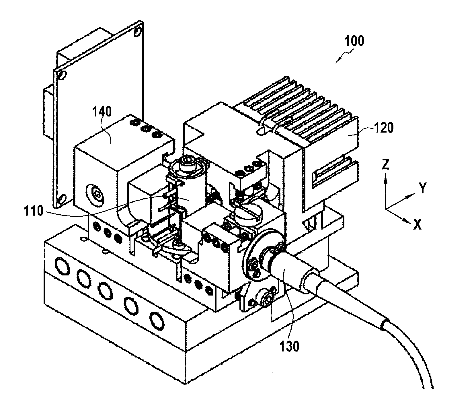
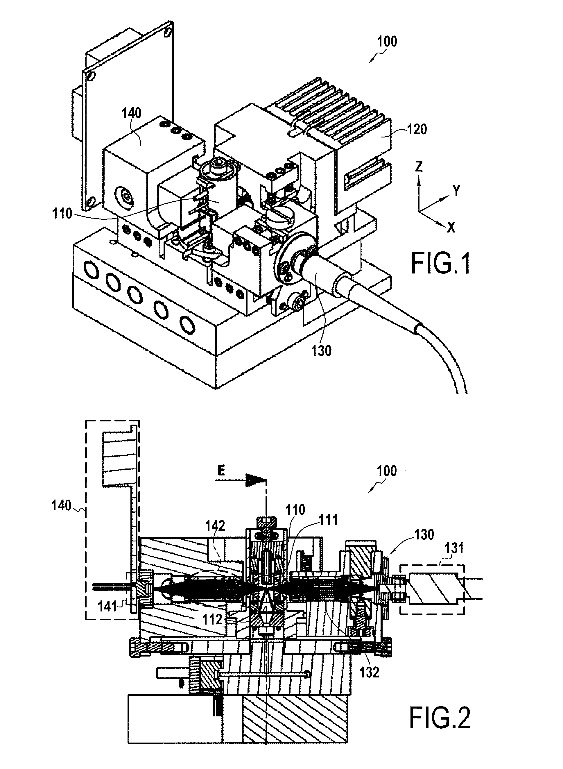
[0068]FIG. 1 is a perspective view of a preferred embodiment of a device 100 of the invention. This device 100 consists of four functional assemblies: an assembly 110 supporting the measurement tank, two assemblies 120 and 130 supporting light sources, and an assembly 140 supporting the light sensor. In the embodiment of the invention shown, the two assemblies 120 and 130 supporting the light sources are mutually perpendicular, one of the two facing the assembly 140 carrying the sensor.

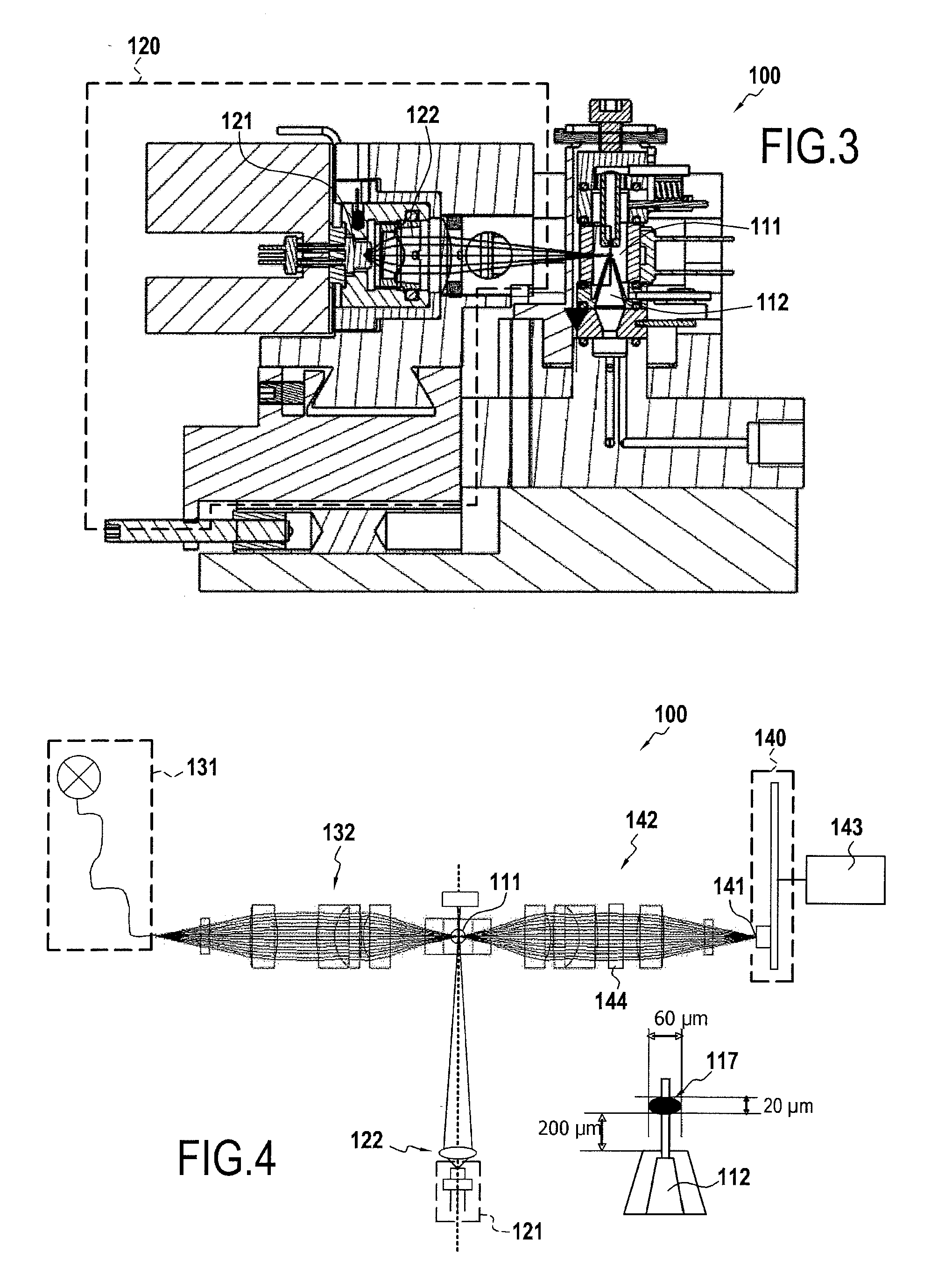
[0069]FIG. 2 is a section of the device 100 on a plane XZ intersecting the measurement plane. The assembly 110 comprises a measuring tank 111 and a nozzle 112 discharging into the measuring tank 111 in order to generate therein the flow of fluid to be analyzed in accordance with the principles of flow cytometry. The assembly 130 comprises a light source 131 and optics 132 providing suitable illumination of the measurement tank.

[0070]The assembly 140 comprises a sensor 141 and optics 142 for appropriat...


PUM


Abstract

The invention relaters to a device (100) for biological analysis by measurement of photoluminescence in a fluid in a measurement tank (111). This device (100) comprises at least two light sources (121, 131) adapted to emit in different spectral areas respectively appropriate for measurement of absorption and fluorescence, and a sensor device (140) comprising a sensor (141), an optical system (142), and filter means (144), which three elements are mutualized in accordance with the invention to enable absorption and/or fluorescence to be measured. In accordance with the invention the internal gain of the sensor (141) is configurable to enable the fluorescence and absorption measurements to be executed sequentially.

Description

BACKGROUND OF THE INVENTION[0001]The field of the present invention is that of biological analysis, in particular hematological analysis. The invention relates to the general field of devices and methods for electro-optic measurements in a fluid present in a measuring tank. Such devices and methods are intended in particular for classifying and counting microscopic objects in a fluid, for example a biological fluid.[0002]To be more precise, the invention relates to devices that use analysis methods based on using electrical and optical measurements to count and distinguish cells present in a sample to be analyzed. In the context of the present invention, this is preferably a blood sample.[0003]With hematopoietic cells, the person skilled in the art knows that volumetric or diffractometric morphological analysis of the cell, including the phenomena of extinction or absorption, enables discrimination of the main cell lines includes erythrocytes (red cells), thrombocytes (platelets), a...

Claims


Application Information

Patent Timeline
IPC IPC(8): G01J1/58G01N21/00
CPCG01N15/1434G01N2015/0073G01N2015/0076G01N2201/1241G01N2015/0084G01N2015/1037G01N2015/008
Inventor MERCHEZ, BENOITBRUNEL, PATRICKNERIN, PHILIPPE
Owner HORIBA ABX SAS
Why Eureka
Try Eureka