Wind turbine generator system and control method of the same

a generator system and wind turbine technology, applied in the direction of electric generator control, process and machine control, instruments, etc., can solve the problems of short-time reduction in wind speed, output power fluctuation, generation efficiency reduction, etc., and achieve the effect of reducing generation efficiency and suppressing output power fluctuation

Active Publication Date: 2011-04-21
MITSUBISHI HEAVY IND LTD
View PDF33 Cites 38 Cited by
  • Summary
  • Abstract
  • Description
  • Claims
  • Application Information

AI Technical Summary

Benefits of technology

[0022]The present invention provides a wind turbine generator system which can suppress output power fluctuation and generation efficiency reduction even when a transient wind null occurs.

Problems solved by technology

One issue for the wind turbine generator system is how to deal with occurrence of a transient wind null, that is, a short-time reduction in the wind speed.
This causes output power fluctuation and generation efficiency reduction.

Method used


Image

  • Wind turbine generator system and control method of the same
  • Wind turbine generator system and control method of the same
  • Wind turbine generator system and control method of the same

Examples


Embodiment Construction

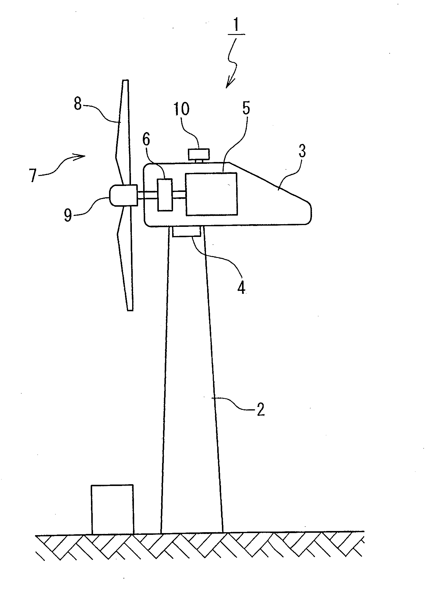
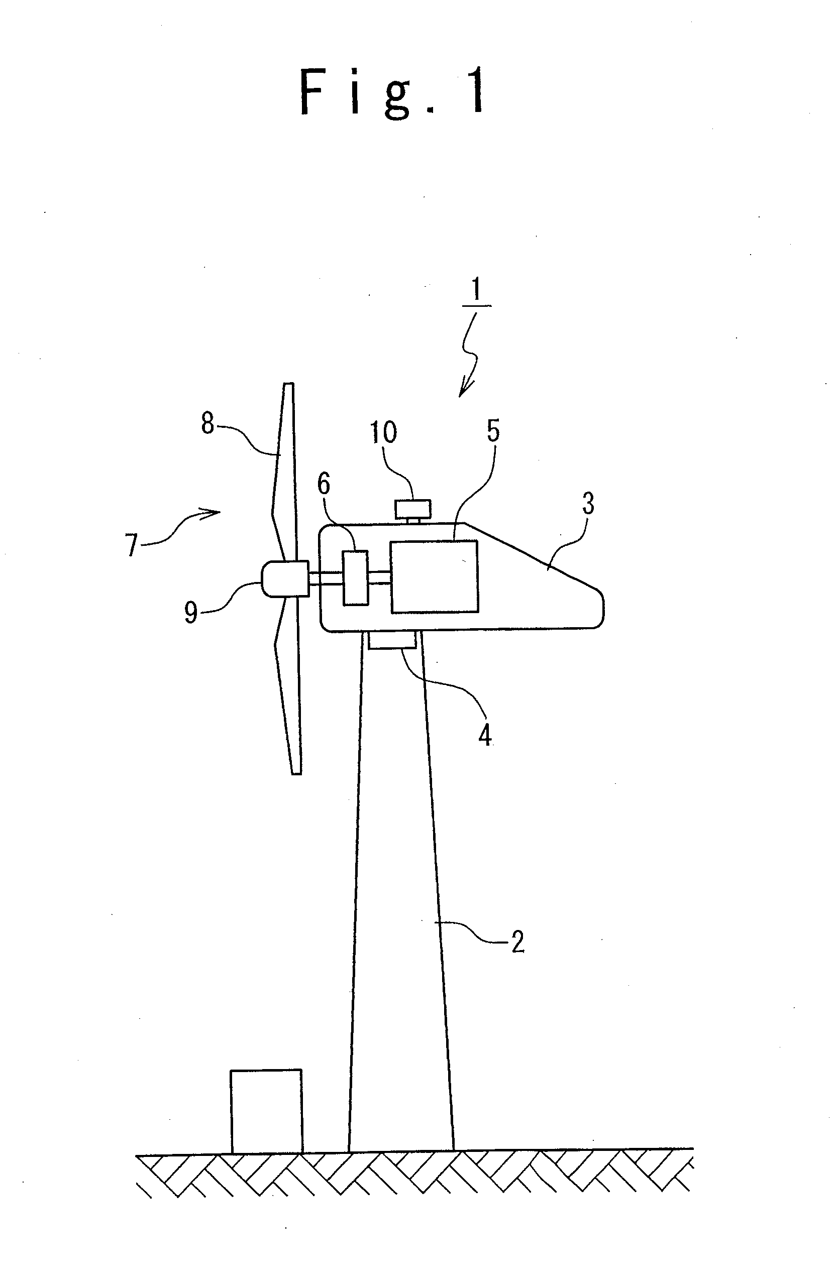
[0035]FIG. 1 is a side view showing the configuration of a wind turbine generator system 1 in one embodiment of the present invention. The wind turbine generator system 1 is provided with a tower 2 and a nacelle 3 provided on the top end of the tower 2. The nacelle 3 is rotatable in the yaw direction and directed to a desired direction by a nacelle rotation mechanism 4. Mounted in the nacelle 3 are a wound-rotor induction generator 5 and a gear 6. The rotor of the wound-rotor induction generator 5 is connected to a wind turbine rotor 7 through the gear 6.

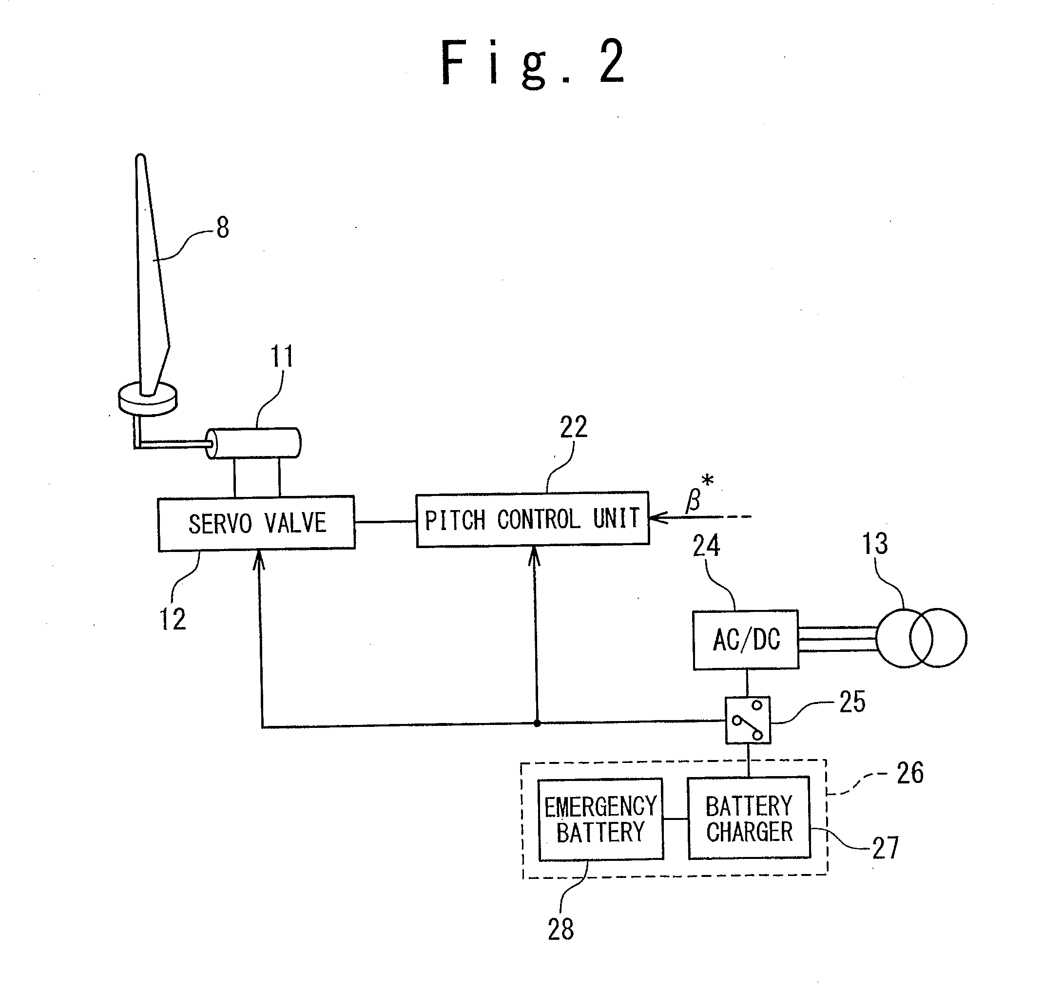
[0036]The wind turbine rotor 7 includes blades 8 and a hub 9 supporting the blades 8. The blades 8 are provided so that the pitch angle thereof is variable. More specifically, as shown in FIG. 2, the hub 9 contains therein hydraulic cylinders 11 driving the blades 8 and servo valves 12 supplying hydraulic pressure to the hydraulic cylinders 11. The hydraulic pressure supplied to the hydraulic cylinders 11 is controlled by the openin...


PUM


Abstract

A wind turbine generator system includes: a wind turbine rotor including a blade having a variable pitch angle; a generator driven by the wind turbine rotor; and a control unit controlling the output power of the generator and the pitch angle of the blade in response to the rotational speed of the wind turbine rotor or the generator. The control unit performs a first control in which the output power is controlled in accordance with a predetermined power-rotational speed curve until the rotational speed is increased to reach a predetermined rated rotational speed, and performs a second control in which the output power is controlled to a predetermined rated power when the rotational speed exceeds the rated rotational speed; the control unit is responsive to the pitch angle for maintaining a state of performing the second control is or for switching to a state of performing the first control, when the rotational speed is reduced below the rated rotational speed after the control unit is once placed into the state of performing the second control.

Description

RELATED APPLICATION[0001]This application is a continuation of International Application No. PCT / JP2008 / 068764, filed on Oct. 16, 2008.BACKGROUND OF THE INVENTION[0002]1. Field of the Invention[0003]The present invention relates to a wind turbine generator system and method for controlling the same, particularly, to control of the output power and the pitch angle of a wind turbine generator system adopting a variable-speed and variable-pitch control method.[0004]2. Description of the Related Art[0005]One of the promising control methods for a wind turbine generator system is a variable-speed and variable-pitch control method, in which the rotational speed of the wind turbine rotor (that is, the rotational speed of the generator) is variable and the pitch angle of the blades is variable. Advantages of the variable-speed and variable-pitch control method include increased energy capture from the wind and decreased output fluctuation.[0006]With respect to the variable-speed and variabl...

Claims


Application Information

Patent Timeline
Patent Type & Authority Applications(United States)
IPC IPC(8): H02P9/04
CPCF03D7/0224F03D7/0272F03D7/028F03D7/043H02P2101/15F05B2270/327F05B2270/706H02P9/04Y02E10/723F05B2270/321Y02E10/72H02P2101/45
Inventor ARINAGA, SHINJIWAKASA, TSUYOSHIMATSUSHITA, TAKATOSHI
Owner MITSUBISHI HEAVY IND LTD
Why Eureka
Try Eureka