Lighting apparatus, backlight apparatus
a backlighting and light-emitting technology, applied in the field of light-emitting devices, can solve the problems of flickering, energy loss of this accumulation, and increased switching loss, and achieve the effect of suppressing flickering owing to the ripple of power
- Summary
- Abstract
- Description
- Claims
- Application Information
AI Technical Summary
Benefits of technology
Problems solved by technology
Method used
Image
Examples
first embodiment
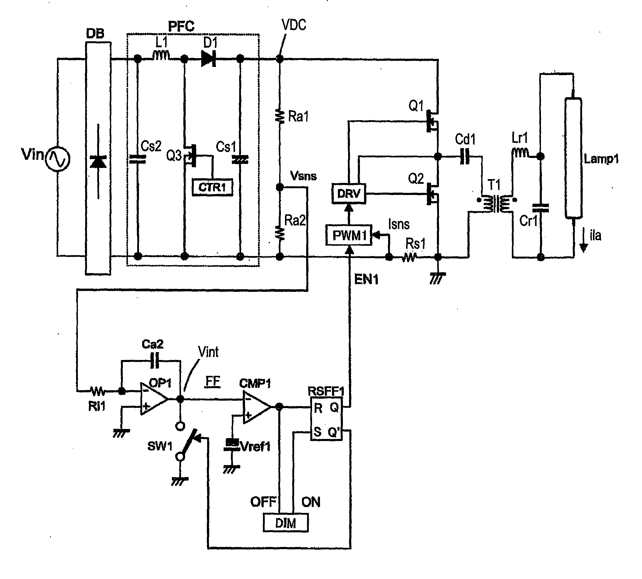
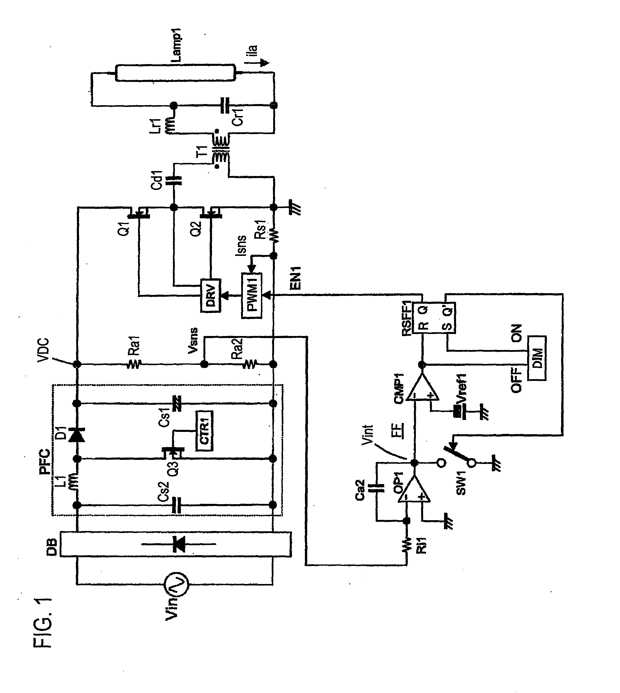
[0049]As shown in FIG. 1, a lighting circuit according to a first embodiment of the present invention includes: a rectifier circuit DB that rectifies a commercial power Vin; and a power factor improvement circuit PFC that steps up and smoothes an output of the rectifier circuit DB.
[0050]The power factor improvement circuit PFC is a well-known step-up chopper circuit. The power factor improvement circuit PFC includes: a capacitor Cs2; a series circuit of an inductor L1 and a switching element Q3; a electrolytic capacitor Cs1; and a chopper control unit CTR1. The capacitor Cs2 is connected in parallel to rectified current output terminals of the rectifier circuit DB. The capacitor Cs2 has a relatively small capacity. The series circuit of an inductor L1 and a switching element Q3 is connected to the rectified current output terminals of the rectifier circuit DB. The electrolytic capacitor Cs1 is for smoothing and is connected in parallel to both ends of the switching element Q3 throug...
second embodiment
[0081]FIG. 4 shows a lighting circuit according to a second embodiment of the present invention. In this embodiment, the lighting time is determined based on an integration value of the input power. In the circuit of FIG. 4, the detection signal Vsns of the direct current voltage VDC and the detection signal Isns of the input current of the inverter circuit are inputted to a multiplier MUL1, and as a result, a power detection signal Wsns is outputted. This power detection signal Wsns is inputted to the integration circuit including the operational amplifier OP1 and the integration capacitor Ca2. When the integration value Vint becomes a reference value Wref1 or less, the comparator CMP1 outputs High, and the inverter circuit turns to a shut-off state.
[0082]A high frequency oscillator OSC1 oscillates a high frequency of which frequency becomes the operation frequency of the inverter circuit. This oscillation is controlled by the enable signal EN1, and the high frequency oscillator OS...
third embodiment
[0085]FIG. 5 shows a lighting circuit according to a third embodiment of the present invention. In this embodiment, a current detection circuit DET2 that detects a lamp current ila is inserted between one end of an inverter circuit output and the lamp Lamp1. In order that an output of the current detection circuit DET2 can become a predetermined value, a lamp current feedback circuit is provided, which is composed of: a feedback control circuit FBC2 that sets a reference voltage (corresponding to Vref1 in FIG. 1) of the feedforward control circuit; a photocoupler PC1 that transmits an output signal of the feedback control circuit FBC2 to the primary side; and a low-pass filter LPF1 that smoothes an output of the photocoupler PC1. Moreover, the inverter circuit includes the high frequency oscillator OSC1 described in the second embodiment. Other configurations are similar to those of the first embodiment.
[0086]In this embodiment, long-term load fluctuations, which are difficult to co...
PUM
 Abstract
Description
Claims
Application Information
 - R&D
- Intellectual Property
- Life Sciences
- Materials
- Tech Scout
- Unparalleled Data Quality
- Higher Quality Content
- 60% Fewer Hallucinations
Browse by: Latest US Patents, China's latest patents, Technical Efficacy Thesaurus, Application Domain, Technology Topic, Popular Technical Reports.
© 2025 PatSnap. All rights reserved.Legal|Privacy policy|Modern Slavery Act Transparency Statement|Sitemap|About US| Contact US: help@patsnap.com


