Energy-Saving Lamp with Remote Control and Button Dimming Feature

a technology of energy-saving lamps and remote control, which is applied in the field of dimmable energy-saving lamps, can solve the problems of circuit failure, circuit failure, and high cost of the above-mentioned button-controlled energy-saving lamp, and achieve the effects of stable performance, low cost and simple structur

Active Publication Date: 2011-04-21
CHANGXING POTEK ELECTRONICS & TECH CO LTD
View PDF5 Cites 21 Cited by
  • Summary
  • Abstract
  • Description
  • Claims
  • Application Information

AI Technical Summary

Benefits of technology

[0033]Compared with existing technologies, this invention is advantageous in that: through the power supply circuit, SCM control module and dimming control module with simple structure, the smooth dimming of the energy-saving lamp tube within broad scope is achieved, moreover, stepless dimming, remote controlled stepless dimming and remote on and off function of ordinary buttons are also realized; furthermore, adopting software detection of button-dimming switches, this invention is provided with lower cost and more stable performance; finally, this invention is more convenient and practical with the luminance memory feature.

Problems solved by technology

However, the button-controlled energy-saving lamp above has complicated circuit structure and high cost.
Furthermore, it can be known from the circuits disclosed in the patent above that the patent only adopts button control, without remote control, the operation is not convenient; besides, the working status detection circuit comprises the 2nd resistor R2, the 1st capacitor C1, the 1st resistor R1, the 1st diode D1, the 2nd capacitor C2, the power on and power down of buttons are tested with the voltage at the 2nd resistor R2, since the charging and discharging of the 1st capacitor C1 and the 2nd capacitor C2 is a process of infinitesimal calculus, which is influenced by the 4th capacitor C4 on ICVCC, the time of charging and discharging cannot correspond to the hand-pressing time in real time, thus there is great time delay, which will necessarily result in dimming failure when the switch is turned on or off rapidly by hand.
Finally, the working power supply of SCM is not reliable, which may cause incapability of the whole circuit, the detail is as follows: the SCM provides the PWM signal and process it into average voltage, which is sent to the voltage-control oscillator, which drives the operation of the serial resonance circuit for turning on or dim the energy-saving lamp tube, it is shown in the actual electrical diagram of the patent above, the working voltage ICVCC of the SCM is the DC voltage from the coupling of inductors L2 and L1, while L2 can only generate working current when the lamp tube is lit after the operation of the voltage-control oscillator and the serial resonance circuit.
When the product is just powered on, the voltage-control oscillator is not working (waiting for PWM signal), and thus the serial resonance circuit cannot work, so there's no working current on L2, thus L1 cannot be coupled to generate the ICVCC voltage, without working voltage, the SCM cannot output PWM signals, thus the circuit can never work with no ICVCC voltage generated.

Method used


Image

  • Energy-Saving Lamp with Remote Control and Button Dimming Feature
  • Energy-Saving Lamp with Remote Control and Button Dimming Feature
  • Energy-Saving Lamp with Remote Control and Button Dimming Feature

Examples


Embodiment Construction

[0045]Detailed description of this invention will be given in combination with the drawings.

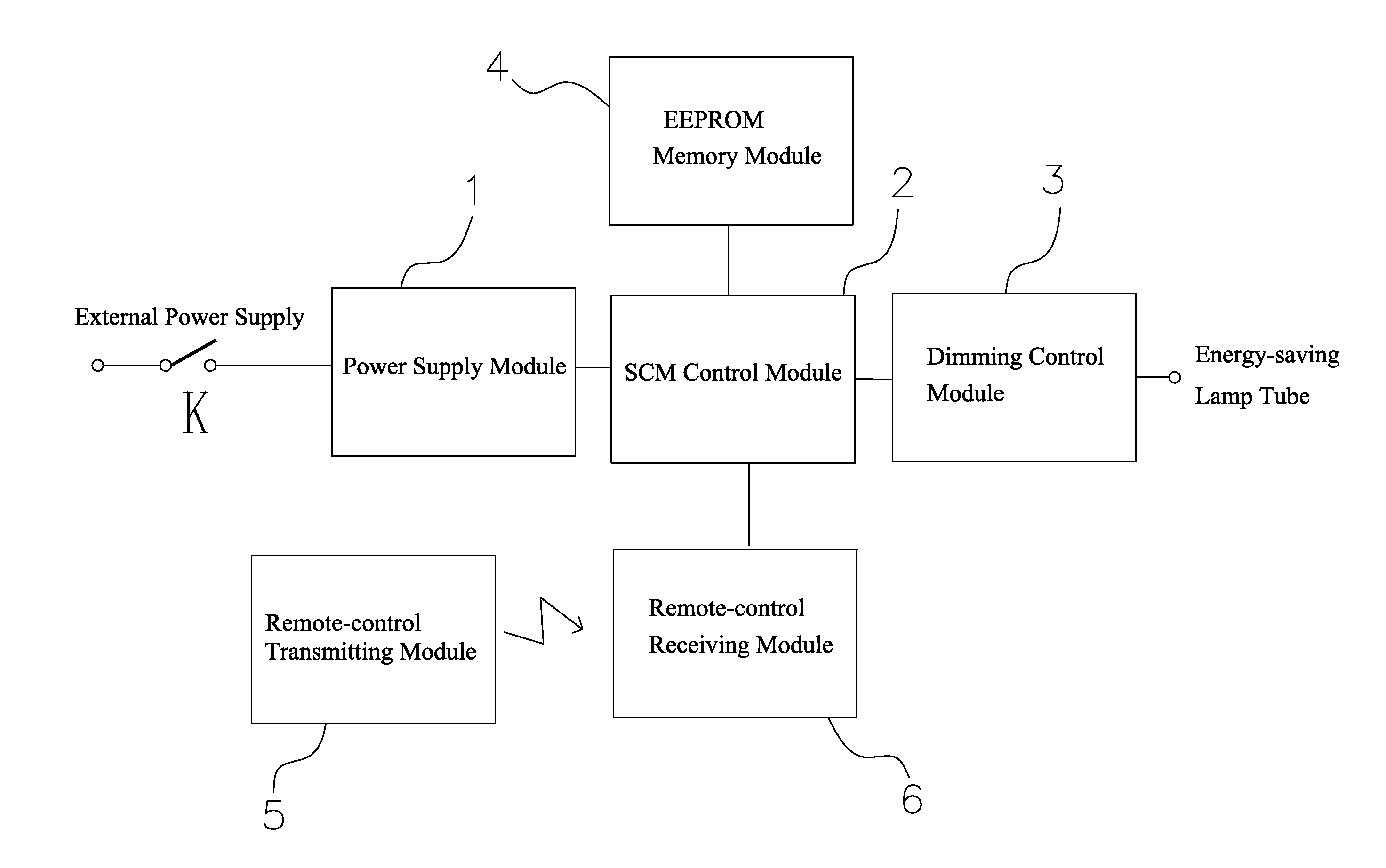
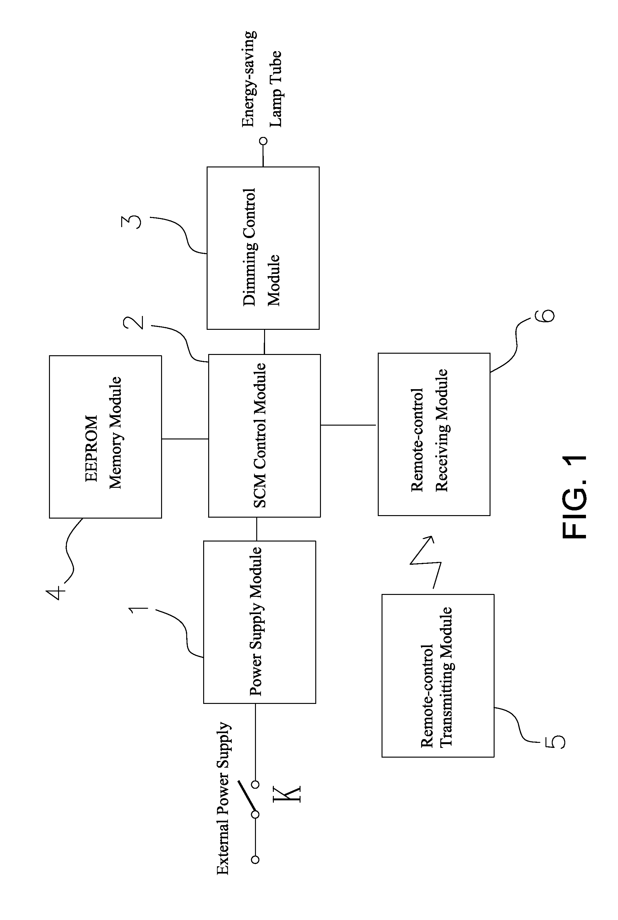
[0046]As shown in FIG. 1, the dimmable energy-saving lamp with remote-control button operation feature comprises one energy-saving lamp tube, one button-dimming switch K, one power supply module, one SCM control module 2, one dimming control module 3, one EEPROM storage module 4, one remote-control transmitting module 5 and one remote-control receiving module 6.

[0047]The 1st terminal of the button-dimming switch K is connected to municipal power, the 2nd terminal of the button-dimming switch K is connected to the 1st capacitor C1 of the power supply circuit, the on and off motions of the button-dimming switch will turn on and off the power supply, thus the SCM will be reset, the on / off status (power on and off) and time will result in different reset modes, the SCM program determines the on / off motions by detecting the reset mode, the SCM control module 2 outputs PMW signals of different widt...


PUM


Abstract

This invention relates to a kind of dimmable energy-saving lamp with remote control and buttons dimming feature comprising: a power supply module (1), one end of which being connected to municipal power supply via the button-dimming switch (K), another end of which being connected to different parts of the whole circuit including the SCM control module (2), an SCM control module (2), the output end of which being connected to the dimming control module (3), the signal output end of said dimming control module (3) being connected to the signal input end of the energy-saving lamp tube as well as the energy-saving lamp tube as the illuminating component; the invention further features: a remote-control transmitting module (5) for transmitting wireless signals at least including dimming signals; a remote-control receiving module (6) for receiving wireless signals at least including dimming signals, the output end of said remote-control receiving module (6) being connected to an input end of said SCM control module (2); adopting remote control and button operation, this invention can achieve smooth dimming of energy-saving lamp tube within a large scope, making it a remote control energy-saving lamp capable of stepless dimming.

Description

CROSS REFERENCE TO RELATED PATENT APPLICATION[0001]This application claims the priority of the Chinese patent application No. 200920269613.X filed on Oct. 20, 2009, which application is incorporated herein by reference.FIELD OF THE INVENTION[0002]This utility relates to a kind of dimmable energy-saving lamp.BACKGROUND OF THE INVENTION[0003]The Chinese Invention Patent under Publication Number CN101309545 (Application number CN200810063600.7) disclosed A Kind of Dimmable Energy-saving Lamp with One-button Control, which comprises the lamp head, the lamp chamber and the energy-saving lamp tube, said lamp chamber being provided with a electronic ballast inside, said electronic ballast being provided with the regulating and filtering circuit, the voltage-control oscillation half-bridge circuit and the serial resonance circuit, the input end of said regulating and filtering circuit being connected to external power supply via said lamp head, the output end of said regulating and filterin...

Claims


Application Information

Patent Timeline
Patent Type & Authority Applications(United States)
IPC IPC(8): H05B37/02
CPCY02B20/40H05B37/0263H05B47/185
Inventor QIN, BING
Owner CHANGXING POTEK ELECTRONICS & TECH CO LTD
Why Eureka
Try Eureka