
Sample processing unit and sample processing method

Inactive Publication Date: 2011-04-21
AOI SEIKI
View PDF9 Cites 4 Cited by
  • Summary
  • Abstract
  • Description
  • Claims
  • Application Information

AI Technical Summary

Benefits of technology

[0008]An object of the present invention is to provide a sample processing unit and sample processing method which are capable of processing a high degree of detection accuracy in the stopper-inserted state.

Problems solved by technology

In the sample processing apparatus configured to carry out, prior to the sample processing, the tube opening processing to open the test tube, and thereafter carry out the sample processing in the manner described above, there is the problem that a lot of time is required for the tube opening processing, and the processing efficiency is poor.
Further, there is the possibility of the sample dispersing or evaporating from the opening part at the upper part of the test tube.
However, the above technique involves the following problem.
That is, there is the problem that a label is attached to the side part of the sample container in some cases, hence it is difficult to detect the state inside the sample in the stopper-inserted state, and the processing accuracy is lowered.

Method used


Image

  • Sample processing unit and sample processing method
  • Sample processing unit and sample processing method
  • Sample processing unit and sample processing method

Examples


second embodiment

[0058]Hereinafter, a second embodiment of the present invention will be described below with reference to FIGS. 7A to 8. FIGS. 7A to 7D are explanatory views of a structure and subdivision processing of a subdivision / dispensing section 35 according to this embodiment. FIG. 8 is a plan view of a chip slope. It should be noted that this embodiment is identical to the first embodiment described previously except that a chip slope 70 is used in the subdivision processing, and hence a description common to the embodiments will be omitted.

[0059]In this embodiment, a subdivision / dispensing section 35 which is a penetration processing unit is constituted by being provided with a chip slope 70.

[0060]The chip slope 70 shown in FIGS. 7A to 7D, and 8 is constituted by being provided with a tubular section 71 having a diameter greater than a nozzle needle 53, and diameter-expansion section 72 continuing above and from the tubular section 71 both of which are provided in an integrated manner. The...

third embodiment

[0064]Hereinafter, a third embodiment of the present invention will be described below with reference to FIGS. 9A to 92, and FIGS. 10A to 10D. FIGS. 9A to 92 are plan views of a stopper body according to this embodiment, and FIGS. 10A to 10D are explanatory views of a structure and subdivision processing of a subdivision / dispensing section 35 according to this embodiment. It should be noted that this embodiment is identical to the first embodiment or second embodiment described previously except that the structure of a stopper body 26 differs from the first or second embodiment, and that an ultrasonic cutter 80 is used, and hence a description common to the embodiments will be omitted.

[0065]As shown in FIGS. 9A to 9C, a stopper body 26 of this embodiment is a seal stopper, and is constituted by including an outer circumferential section 26a, and central section 26b both of which are formed integral with each other. The outer circumferential section 26a is constituted of, for example...


PUM


Abstract

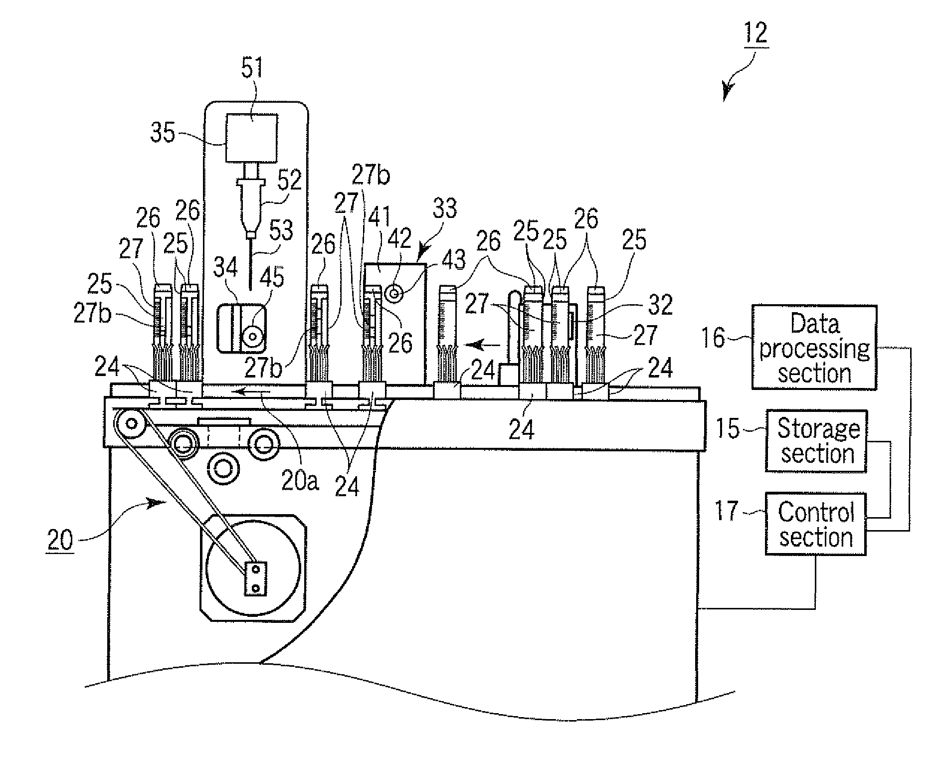
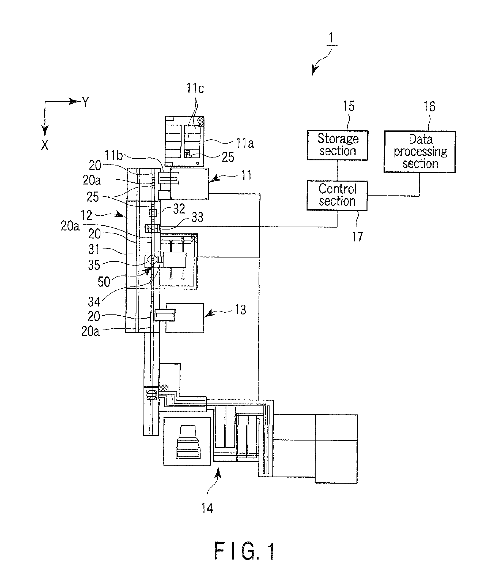
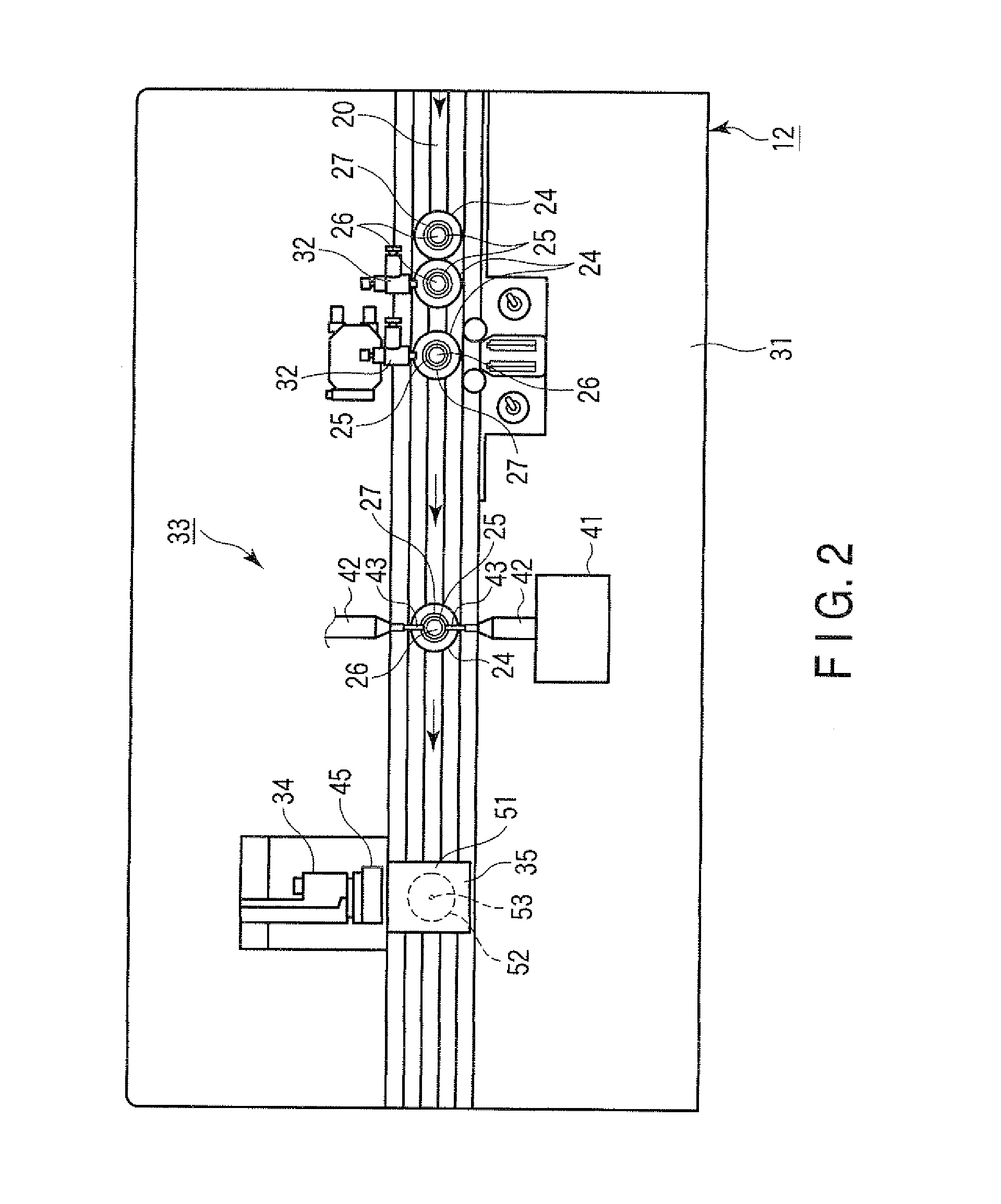
An example of the invention is a sample processing unit having, a subdivision / dispensing section including a nozzle needle configured to be able to penetrate a stopper body fitted in a sample container in which a sample can be contained, and configured to subject the sample container or the sample to processing, a detection unit configured to detect a state of the sample or the sample container at the time of the processing, and a label removal unit configured to remove at least part of a label attached to a side part of the sample container prior to the detection.

Description

CROSS-REFERENCE TO RELATED APPLICATIONS[0001]This application is based upon and claims the benefit of priority from prior Japanese Patent Applications No. 2009-241490, filed Oct. 20, 2009; and No. 2010-114628, filed May 18, 2010, the entire contents of both of which are incorporated herein by reference.BACKGROUND OF THE INVENTION[0002]1. Field of the Invention[0003]The present invention relates to a sample processing unit and sample processing method configured to carry out processing in a sample container in which a sample is contained.[0004]2. Description of the Related Art[0005]As a sample processing apparatus configured to carry out processing in a sample container containing therein a sample, an analysis apparatus or the like configured to extract a blood serum separated from blood acquired by, for example, blood drawing through a centrifugal separation process as a sample, and carry out analysis processing by infusing a reagent into the sample to detect the reaction is known (...

Claims


Application Information

Patent Timeline
IPC IPC(8): G01N1/00G01N33/48
CPCG01N33/491G01N35/00Y10T436/25G01N2035/00752G01N2035/1025G01N35/1079
Inventor ITOH, TERUAKI
Owner AOI SEIKI
Learn More