
Golf ball

a golf ball and ball technology, applied in the field of golf balls, to achieve the effect of reducing the slipping of the golf ball, great spin rate and great spin ra

Active Publication Date: 2011-04-21
SUMITOMO RUBBER IND LTD
View PDF11 Cites 16 Cited by
  • Summary
  • Abstract
  • Description
  • Claims
  • Application Information

AI Technical Summary

Benefits of technology

[0018](2) gripping property for the golf ball of the club face. Short irons have a great loft angle and deep grooves. On the other hand, drivers have a small loft angle and shallow grooves. There also exist drivers having no groove at the center of the face. Short irons result in a low head speed, whereas drivers result in a high head speed. The spin rate of golf balls upon hitting with a short iron greatly depends on the extent of invasion of the cover into the groove. The spin rate of the golf balls upon hitting with a driver greatly depends on the gripping property for the golf ball of the face. When the golf ball according to the present invention is hit with a short iron, the cover sufficiently invades into the grooves of the face since this golf ball has a soft cover. This invasion suppresses slipping of the golf ball on the face. By suppressing the slipping, a great spin rate is achieved. This golf ball achieves a great spin rate of when hit with an iron club that conforms to the new rules. A great spin rate of this golf ball is also achieved upon hitting with a short iron on the rough. Moreover, a great spin rate of this golf ball is also achieved upon hitting with a short iron in a wet state. This cover is thin, and the mid layer is harder than the cover. When this golf ball is hit with a driver, the mid layer affects a deformation behavior. This mid layer suppresses the spin upon hitting with a driver. Suppression of the spin leads to attainment of a great flight distance. This golf ball is excellent in the flight performances upon hitting with a driver, and is also excellent in the control performances upon hitting with a short iron.

Problems solved by technology

(1) the extent of invasion of the cover into the groove of the club face; and
(2) gripping property for the golf ball of the club face. Short irons have a great loft angle and deep grooves. On the other hand, drivers have a small loft angle and shallow grooves. There also exist drivers having no groove at the center of the face. Short irons result in a low head speed, whereas drivers result in a high head speed. The spin rate of golf balls upon hitting with a short iron greatly depends on the extent of invasion of the cover into the groove. The spin rate of the golf balls upon hitting with a driver greatly depends on the gripping property for the golf ball of the face. When the golf ball according to the present invention is hit with a short iron, the cover sufficiently invades into the grooves of the face since this golf ball has a soft cover. This invasion suppresses slipping of the golf ball on the face. By suppressing the slipping, a great spin rate is achieved. This golf ball achieves a great spin rate of when hit with an iron club that conforms to the new rules. A great spin rate of this golf ball is also achieved upon hitting with a short iron on the rough. Moreover, a great spin rate of this golf ball is also achieved upon hitting with a short iron in a wet state. This cover is thin, and the mid layer is harder than the cover. When this golf ball is hit with a driver, the mid layer affects a deformation behavior. This mid layer suppresses the spin upon hitting with a driver. Suppression of the spin leads to attainment of a great flight distance. This golf ball is excellent in the flight performances upon hitting with a driver, and is also excellent in the control performances upon hitting with a short iron.

Method used


Image

  • Golf ball
  • Golf ball

Examples


example 1

[0104]A rubber composition was obtained by kneading 100 parts by weight of a high-cis polybutadiene (“BR-730”, trade name, available from JSR Corporation), 34 parts by weight of zinc diacrylate, 5 parts by weight of zinc oxide, an adequate amount of barium sulfate, 0.5 parts by weight of diphenyl disulfide and 0.8 parts by weight of dicumyl peroxide (NOF Corporation). This rubber composition was placed into a mold having upper and lower mold half each having a hemispherical cavity, and heated at 170° C. for 18 minutes to obtain a core having a diameter of 39.60 mm. The amount of barium sulfate was adjusted such that a golf ball having a weight of 45.6 g was obtained.

[0105]A resin composition (I) was obtained by kneading 50 parts by weight of an ionomer resin (“Himilan® 1605”, supra), 50 parts by weight of other ionomer resin (“Himilan® AM7329”, supra), 10 parts by weight of zinc oxide (“Panatetra WZ-0501”, supra) and 4 parts by weight of titanium dioxide in a biaxial kneading extrud...


PUM


Abstract

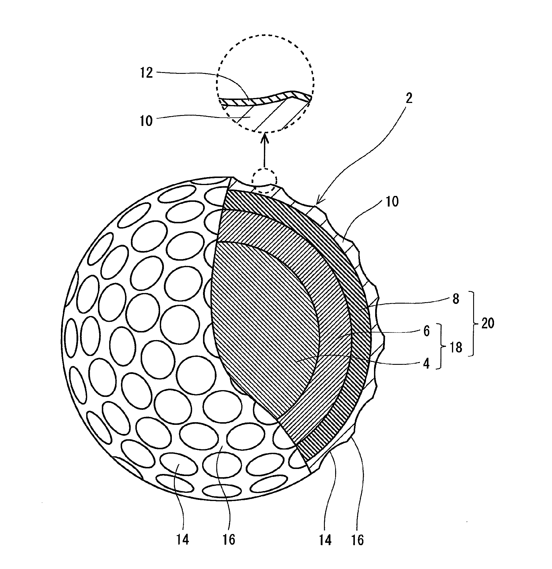
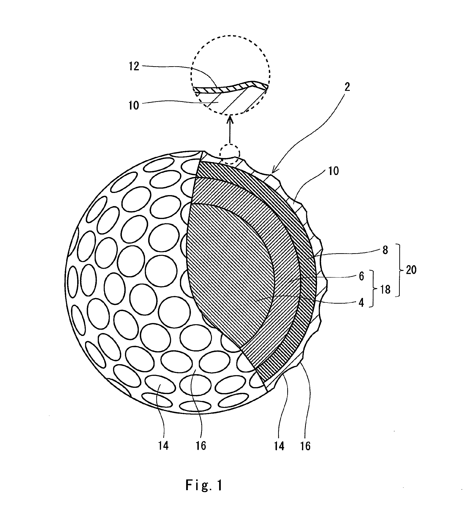
Golf ball 2 has spherical core 4, surrounding layer 6 situated on the external side of the core 4, mid layer 8 situated on the external side of the surrounding layer 6, cover 10 situated on the external side of the mid layer 8, and paint layer 12 situated on the external side of the cover 10. The mid layer 8 has a thickness Tm of 0.1 mm or greater and 1.2 mm or less. The ratio (Tc / Tm) of the thickness Tc of the cover 10 to the thickness Tm of the mid layer 8 is no greater than 0.50. The cover 10 has a Shore D hardness Hc of no greater than 35. The Shore D hardness Hm of the mid layer 8 is greater than the Shore D hardness Hc of the cover 10. The base material of the surrounding layer 6 is an ionomer resin. The base material of the mid layer 8 is a polyurethane. The base material of the cover 10 is a polyurethane.

Description

[0001]This application claims priority on Patent Application No. 2009-237818 filed in JAPAN on Oct. 15, 2009. The entire contents of this Japanese Patent Application are hereby incorporated by reference.BACKGROUND OF THE INVENTION[0002]1. Field of the Invention[0003]The present invention relates to golf balls. More particularly, the present invention relates to multi-piece golf balls having a core, a surrounding layer, a mid layer and a cover.[0004]2. Description of the Related Art[0005]Top concern to golf players for golf balls is their flight performances. The golf players particularly place great importance on flight distance attained upon shots with a driver. Use of a golf ball which can attain a great flight distance upon shots with a driver enables the golf player to hit the second shot from a point near the green. The flight distance attained upon shots with a driver correlates with the spin rate. Golf balls accompanied by a small spin rate are excellent in flight performance...

Claims


Application Information

Patent Timeline
Patent Type & Authority Applications(United States)
IPC IPC(8): A63B37/02A63B37/12
CPCA63B37/0022A63B37/0031A63B37/0033A63B37/0043A63B37/0092A63B37/0062A63B37/0063A63B37/0076A63B37/0045A63B37/00922A63B37/00622A63B37/00621
Inventor NAKAMURA, HIROTAKAOHAMA, KEIJIENDO, SEIICHIRO
Owner SUMITOMO RUBBER IND LTD
Learn More