Adiabatic compressed air energy storage system with multi-stage thermal energy storage

a technology of compressed air and energy storage, which is applied in the direction of hot gas positive displacement engine plants, machines/engines, engine fuctions, etc., can solve the problems of large duty of tes units, high temperature and high pressure, and high temperature and high pressure, and achieves long development time, increased cost, and high efficiency.

Inactive Publication Date: 2011-04-28
GENERAL ELECTRIC CO
View PDF12 Cites 105 Cited by
  • Summary
  • Abstract
  • Description
  • Claims
  • Application Information

AI Technical Summary

Problems solved by technology

The use of a single TES unit results in the TES unit being forced to operate at a high temperature and high pressure.
The high temperature, high pressure, and large duty of the TES unit pose engineering challenges with regard to material, thermal expansion, heat losses, size and mechanical stresses.
The need to address these engineering challenges leads to increased cost and long development times and presents a steep market barri

Method used


Image

  • Adiabatic compressed air energy storage system with multi-stage thermal energy storage
  • Adiabatic compressed air energy storage system with multi-stage thermal energy storage
  • Adiabatic compressed air energy storage system with multi-stage thermal energy storage

Examples


Embodiment Construction

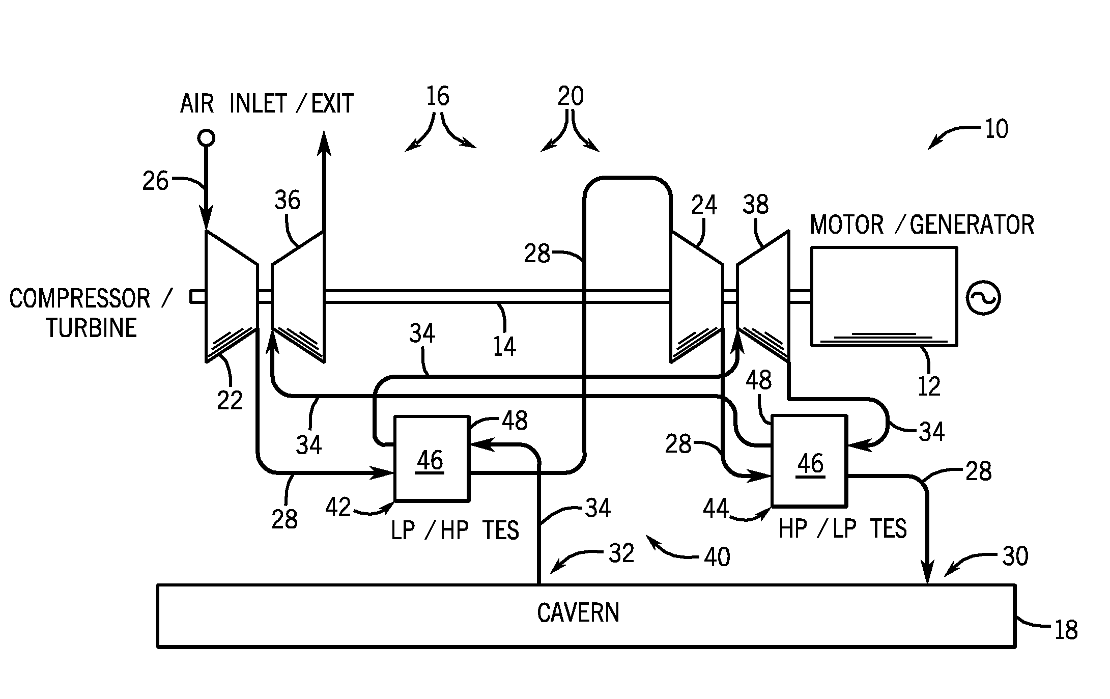
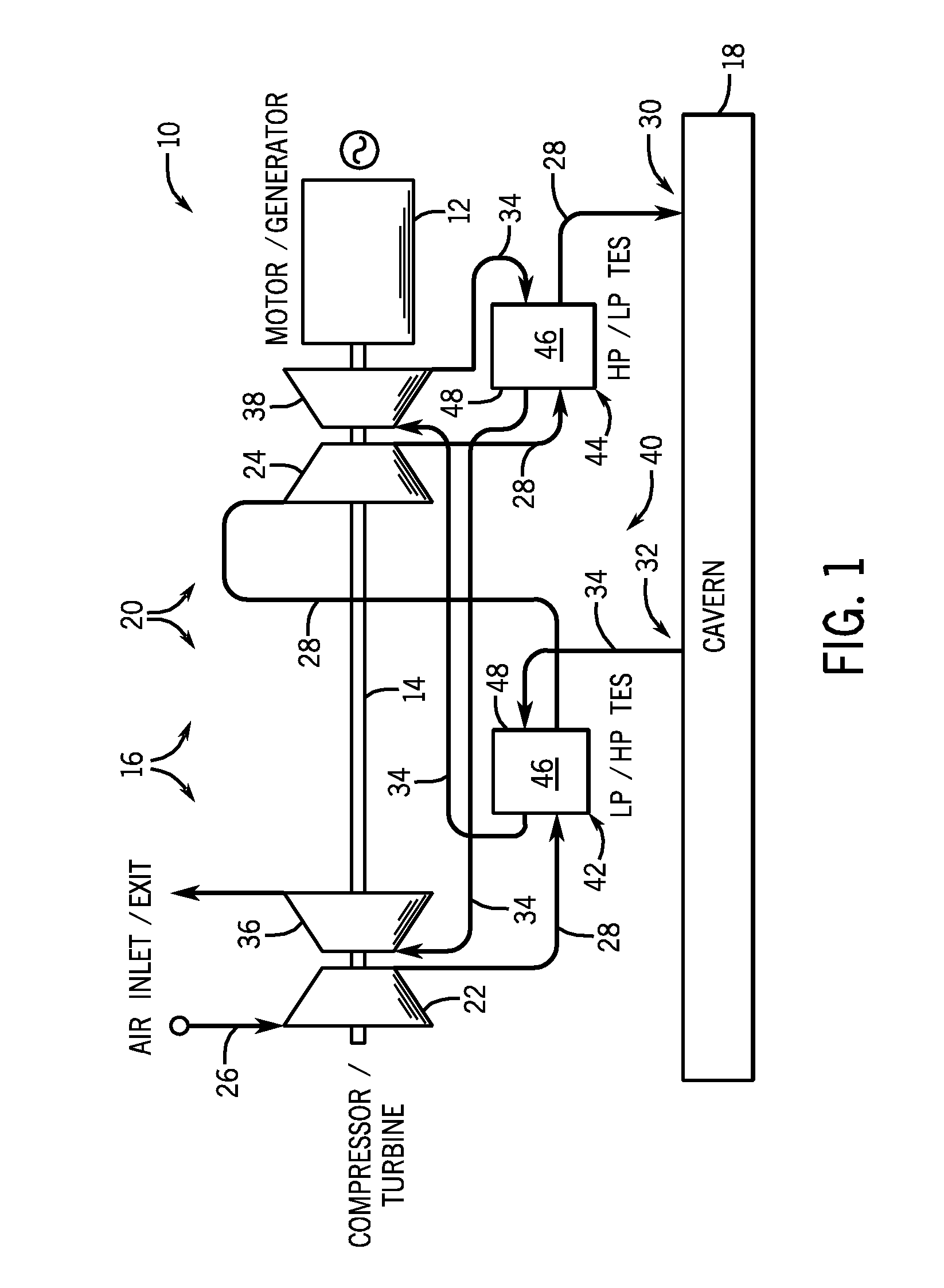
[0019]According to embodiments of the invention, a multi-stage thermal energy storage (TES) system is provided to cool and heat air in an adiabatic compressed air energy storage (ACAES) system. The multi-stage TES system includes a plurality of TES units whose operating conditions can be switched or reversed between operation of the ACAES system in a compression mode and an expansion mode.

[0020]Referring to FIG. 1, a block schematic diagram of an adiabatic compressed air energy storage (ACAES) system 10 is shown according to an embodiment of the invention. ACAES system 10 includes a motor-generator unit 12 (which may be a combined unit or separate units), a driving shaft 14, a compression system or train 16, a compressed air storage volume or cavern 18, and a turbine system or train 20.

[0021]Motor-generator unit 12 is electrically connected to, for example, a baseload power generating plant (not shown) to receive power therefrom. Motor-generator unit 12 and drive shaft 14 are select...


PUM


Abstract

An ACAES system operable in a compression mode and an expansion mode of operation is disclosed and includes a compressor system configured to compress air supplied thereto and a turbine system configured to expand compressed air supplied thereto, with the compressor system including a compressor conduit and the turbine system including a turbine conduit. The ACAES system also includes a plurality of thermal energy storage (TES) units positioned on the compressor and turbine conduits and configured to remove thermal energy from compressed air passing through the compressor conduit and return thermal energy to air passing through the turbine conduit. The compressor conduit and the turbine conduit are arranged such that at least a portion of the plurality of TES units operate at a first pressure state during the compression mode of operation and at a second pressure state different from the first pressure state during the expansion mode of operation.

Description

BACKGROUND OF THE INVENTION[0001]Embodiments of the invention relate generally to compressed air energy storage (CAES) systems and, more particularly, to a multi-stage thermal energy storage (TES) system in an adiabatic CAES system.[0002]Air compression and expansion systems are used in a multitude of industries for a variety of applications. For example, one such application is the use of air compression and expansion systems for storing energy. Compressed air energy storage (CAES) systems typically include a compression train having a plurality of compressors that compress intake air and provide the compressed intake air to a cavern, underground storage, or other compressed air storage component. The compressed air is then later used to drive turbines to produce electrical energy. During operation of the compression stage of a CAES system, the compressed intake air is typically cooled. During operation of the expansion stage, air is discharged from underground storage through heat...

Claims


Application Information

Patent Timeline
IPC IPC(8): F02C6/14F02C6/16F02C1/05
CPCF02C1/02F02C1/04F05D2260/211Y02E60/15F02C6/16Y02E60/16
Inventor FREUND, SEBASTIAN W.
Owner GENERAL ELECTRIC CO
Why Eureka
Try Eureka