Structure of automatic foam soap dispenser

a technology of automatic foam soap dispenser and foam reservoir, which is applied in the direction of liquid transfer devices, instruments, volume meters, etc., can solve the problems of reducing the lifetime of the valve body, and achieve the effects of prolonging the lifetime of the soap reservoir, reducing the wear caused by torsion, and improving the durability of the transmission gear s

Inactive Publication Date: 2011-04-28
HOKWANG IND
View PDF9 Cites 24 Cited by
  • Summary
  • Abstract
  • Description
  • Claims
  • Application Information

AI Technical Summary

Benefits of technology

[0012]1. According to the present invention, the soap reservoir can be in an upright position with the pressing head at top, and by the extension pipe, the foam nozzle can be mounted at the inner bottom of the covering housing, in the result that the foam outlet is distant from a valve body of the soap reservoir, so that the foam will not be gathered around the foam outlet, thereby preventing the foam suction, which may influence the movement of the valve body, and thus prolonging the lifetime of the soap reservoir.
[0013]2. Through the outlet extension portion mounted around the foam outlet at the bottom of the foam nozzle and the adhesion plate surrounding the outlet extension portion, the

Problems solved by technology

1. In the conventional automatic foam soap dispenser, the soap reservoir is designed to be upside down, so that when the soap reservoir is pressed, the valve body compresses air into the soap reservoir. When the net is mounted inside the outlet, the air will push the soap toward the outlet and then pass through the net for making foam. However, since the valve body is close to the net and the net is close to the outlet, the foam is easily gathered around the outlet and then

Method used


Image

  • Structure of automatic foam soap dispenser
  • Structure of automatic foam soap dispenser
  • Structure of automatic foam soap dispenser

Examples


Embodiment Construction

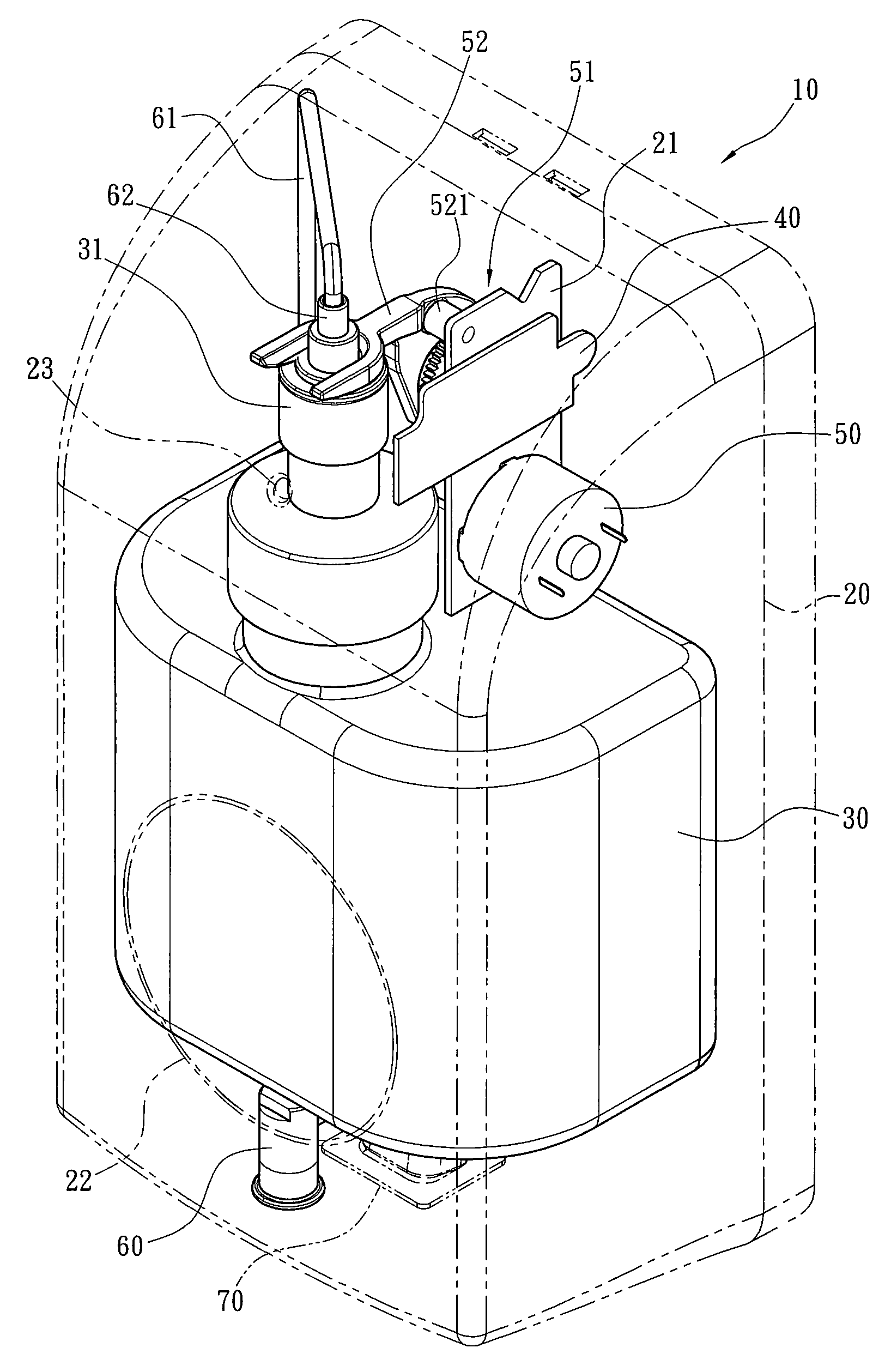
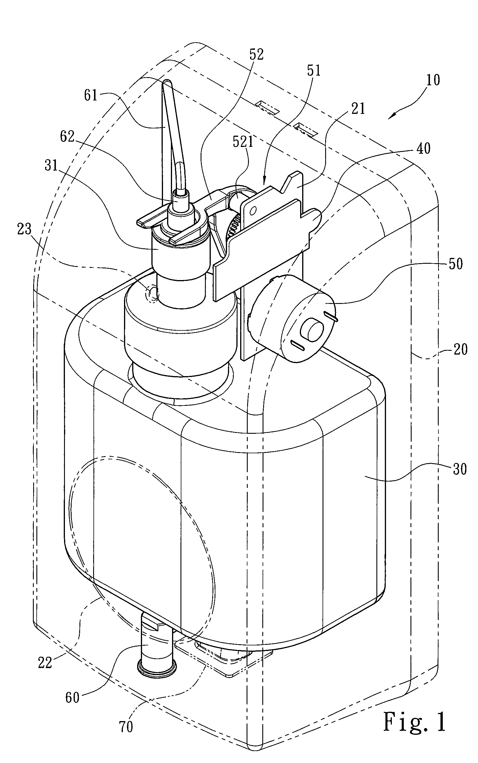
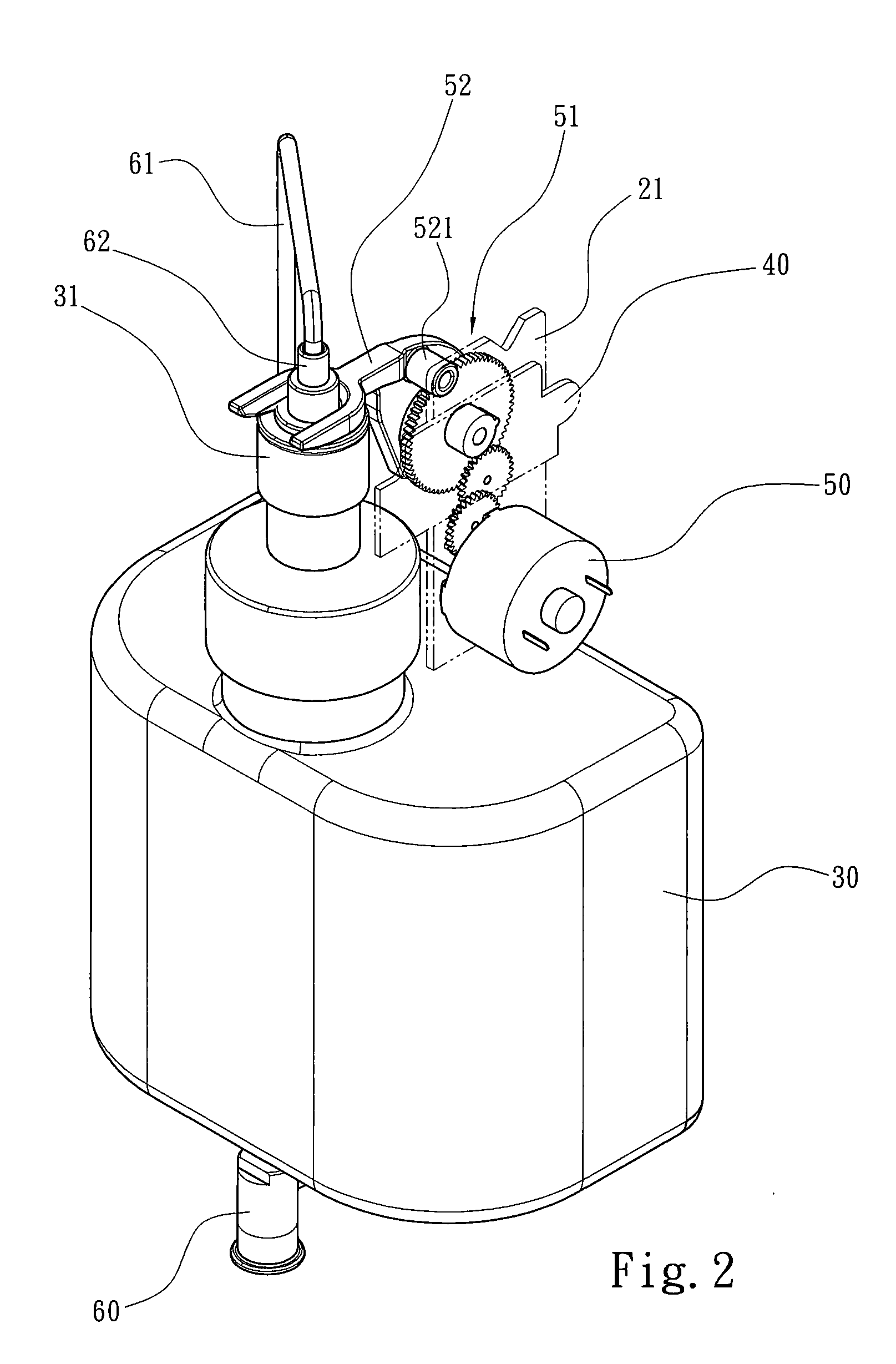
[0021]Please refer to FIGS. 1 to 3 for showing the three-dimensional appearance and the decomposition details of the automatic soap dispenser according to the present invention. As shown, the automatic foam soap dispenser 10 of the present invention includes a covering housing 20 opened downwardly and a transparent window 22 for exposing a pressing-typed soap reservoir 30, and a power indication light 23 for showing the power condition of a control circuit board 40. The covering housing 20 accommodates the pressing-typed soap reservoir 30, the control circuit board 40 electrically connected to a power source, a motor 50 controlled by the control circuit board 40, and a sensor 70 for sensing the approach of an external object and feedbacking a signal to the control circuit board 40 so as to trigger the motor 50 to turn and press the pressing-typed soap reservoir 30. Here, the soap reservoir 30, at the top thereof, has a pressing head 31, which can be pressed downwardly, and the press...


PUM


Abstract

The present invention provides an automatic foam soap dispenser used for single soap reservoir which is pressed from top to down. The automatic foam soap dispenser includes a covering housing opened downwardly for accommodating a pressing-typed soap reservoir, a control circuit board, a motor, and a sensor. The soap reservoir has a pressing head at the top thereof, the pressing head is communicated with a connecting head, and the connecting head has an extension pipe to communicate with a foam nozzle, which is mounted at the bottom of the covering housing. Moreover, an extension fixing board is extended inside the covering housing for mounting a transmission gear set, which is driven by the motor to turn, and a swinging pressing board, wherein the transmission gear set has a cam, and a first end of the swinging pressing board is pivotally connected to the cam and the transmission gear set, and a second end of the swinging pressing board is leaned on the pressing head or the connecting head. Accordingly, the present invention not only complies with the usual practice of downward soap output, but also prolongs the lifetime of the soap reservoir and the soap dispenser, and the problem of soap dropping caused from the remaining foam soap is also solved.

Description

FIELD OF THE INVENTION[0001]The present invention is related to the structure of an automatic soap dispenser, and more particularly, to an automatic foam soap dispenser used for a soap bottle pressed downwardly (such as, the pressing bottles for hand soap and shampoo found in the market).BACKGROUND OF THE INVENTION[0002]Owing to the development of technology and the improvement of life quality, the manual soap dispenser has been replaced by the automatic soap dispenser with the sensing technology.[0003]The current automatic soap dispenser, as disclosed in a R.O.C patent No. M328853, entitled “Soap dispensing mechanism for automatic soap dispenser”, includes a driving device, composed of a motor and a gear set, for driving a tube pressing lever to press a soap tube linked to a soap reservoir so as to output the soap. The tube pressing lever, which is pivotally connected to a protruded axle of a substrate in the driving device, has a curved side and an opposite flat side, and the curv...

Claims


Application Information

Patent Timeline
IPC IPC(8): B67D7/08B67D7/06B67D7/22B67D7/56
CPCA47K5/16
Inventor LIAO, WEI-TATSAI, HUANGLEE, KUO-CHOUHUANG, TSAN-CHANG
Owner HOKWANG IND
Why Eureka
Try Eureka