
Light emitting device and light emitting device package

a technology of light emitting devices and light emitting devices, which is applied in the direction of semiconductor devices, basic electric elements, electrical equipment, etc., can solve the problems of damage to the active layer formed in the light emitting area, and achieve the effect of preventing light absorption from being lowered and preventing the damage of the light emitting devi

Inactive Publication Date: 2011-04-28
LG INNOTEK CO LTD
View PDF9 Cites 5 Cited by
  • Summary
  • Abstract
  • Description
  • Claims
  • Application Information

AI Technical Summary

Benefits of technology

[0013]The embodiment provides a light emitting device, a light emitting device package, and a lighting system, capable of preventing the light emitting device from being damaged due to ESD while preventing light absorption from being lowered.
[0014]The embodiment provides a light emitting device, a light emitting device package, and a lighting system, capable of improving light extraction efficiency while enhancing current spreading efficiency.

Problems solved by technology

According to the related art, a current may flow reversely when electrostatic discharge (ESD) occurs, thereby causing damage to an active layer formed in a light emitting area.

Method used


Image

  • Light emitting device and light emitting device package
  • Light emitting device and light emitting device package
  • Light emitting device and light emitting device package

Examples


embodiment

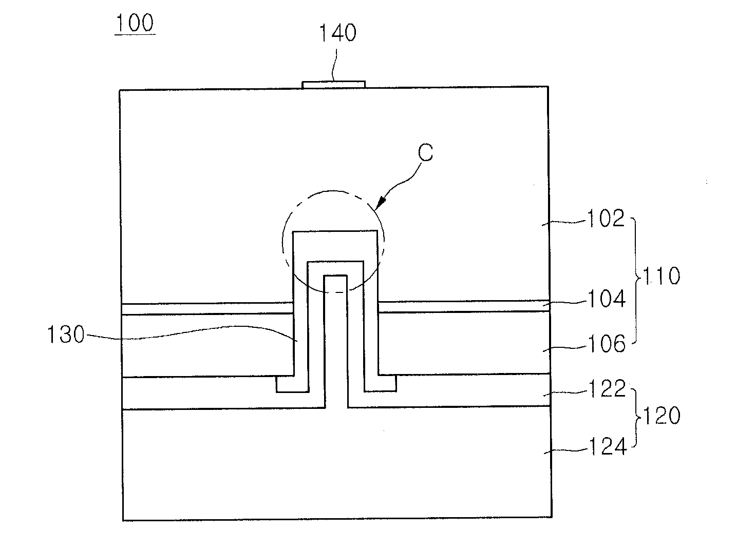
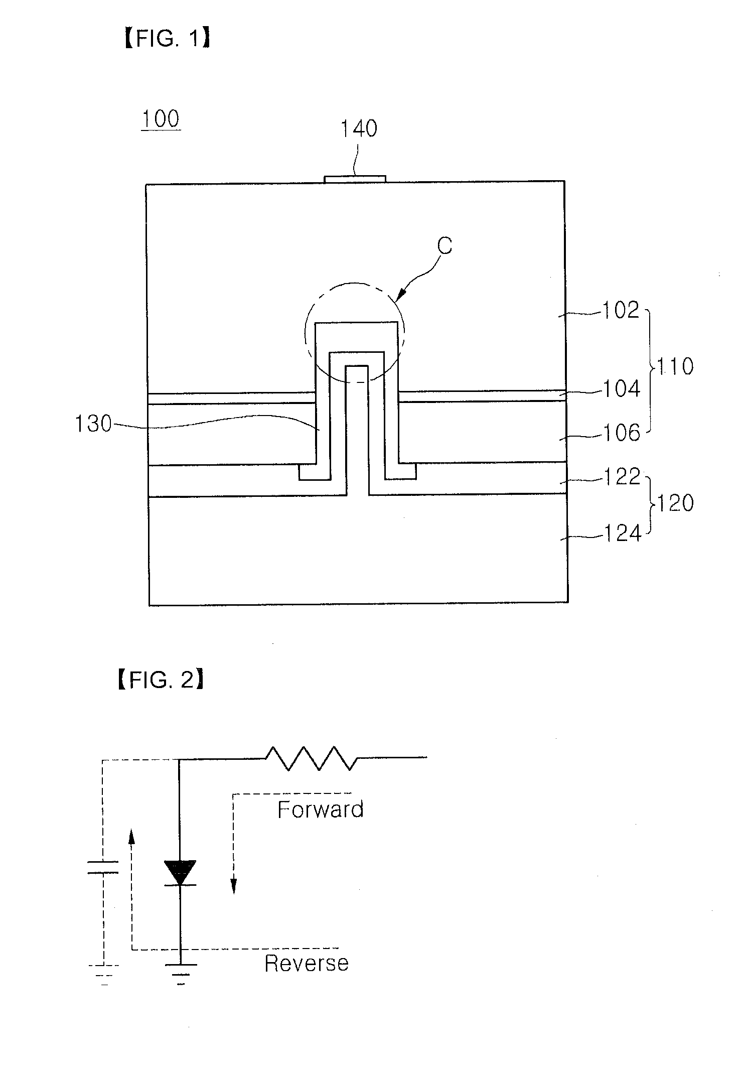
[0030]FIG. 1 is a sectional view showing a light emitting device according to a first embodiment, and FIG. 2 is a circuit diagram showing the light emitting device according to the embodiment.

[0031]The light emitting device according to the embodiment includes a light emitting structure 110 including a first conductive semiconductor layer 102, an active layer 104, and a second conductive semiconductor layer 106, a dielectric layer 130 formed in a cavity defined by removing a portion of the light emitting structure 110, and a second electrode layer 120 formed on the dielectric layer 130.

[0032]According to the embodiment, the first conductive semiconductor layer 102, the dielectric layer 130, and the second electrode layer 120 can carry out the function of a capacitor C. Although one capacitor C is shown in FIG. 1, the embodiment is not limited thereto. According to another embodiment, a plurality of capacitors may be provided.

[0033]In the light emitting device and a method of manufac...


PUM


Abstract

Disclosed are a light emitting device, a light emitting device package, and a lighting system. The light emitting device includes a light emitting structure including a second conductive semiconductor layer, an active layer over the second conductive semiconductor layer, and a first conductive semiconductor layer over the active layer dielectric layer in a cavity defined by removing a portion of the light emitting structure, and a second electrode layer over the dielectric layer.

Description

CROSS-REFERENCE TO RELATED APPLICATION[0001]This application claims under 35 U.S.C. §119 to Korean Patent Application No. 10-2009-0100653 filed Oct. 22, 2009, which is hereby incorporated by reference in its entirety.BACKGROUND[0002]The embodiment relates to a light emitting device, a light emitting device package, and a lighting system.[0003]A light emitting device (LED) includes a p-n junction diode having a characteristic of converting electric energy into optical energy. The p-n junction diode can be formed by combining group III-V elements of the periodic table. The LED can represent various colors by adjusting the compositional ratio of compound semiconductors.[0004]When a forward voltage is applied to the LED, electrons of an n layer are combined with holes of a p layer, so that energy corresponding to an energy gap between a conduction band and a valance band may be generated. This energy is mainly realized as heat or light, and the LED emits the energy as the light.[0005]A ...

Claims


Application Information

Patent Timeline
Patent Type & Authority Applications(United States)
IPC IPC(8): H01L33/60
CPCH01L27/15H01L33/145H01L33/20H01L33/382H01L2224/48091H01L2924/00014H01L33/405
Inventor HWANG, SUNG MIN
Owner LG INNOTEK CO LTD
Learn More