
Device for increasing container volume

Active Publication Date: 2011-04-28
CLAAS SELBSTFAHRENDE ERNTEMASCHINEN GMBH
View PDF3 Cites 14 Cited by
  • Summary
  • Abstract
  • Description
  • Claims
  • Application Information

AI Technical Summary

Benefits of technology

[0006]It is an object of the present invention to provide a device for increasing the volume of a container, which provides the container with additional capacity, is operable in a stable and wear-resistant manner and is completely automatically operable.
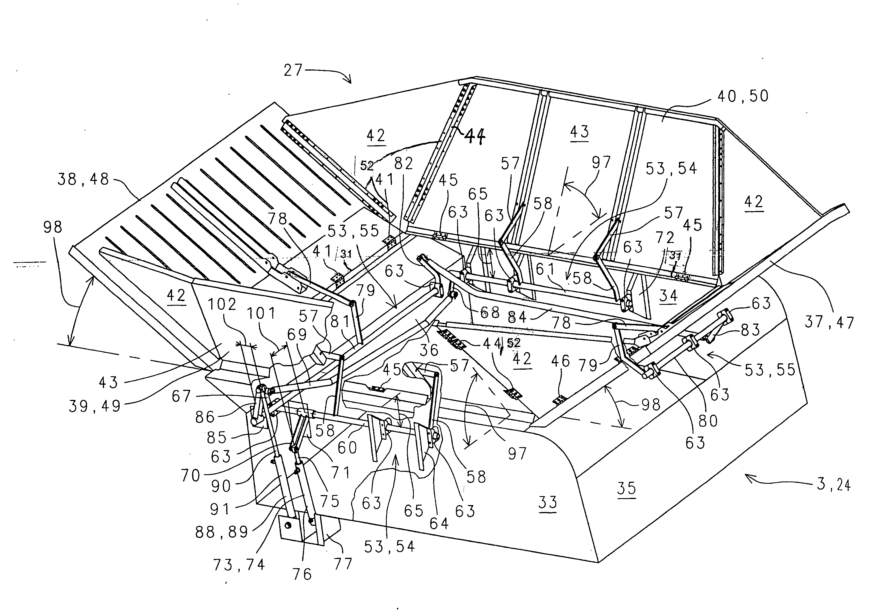
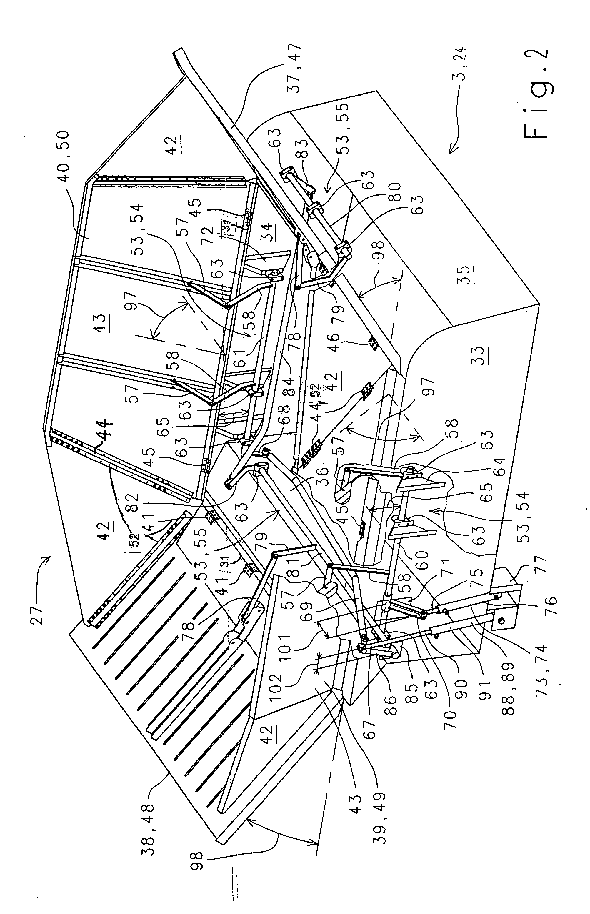
[0010]The container capacity is advantageously increased in the filling or operating configuration since each extension element is pivoted from the flat closed position into an erect filling position beyond a vertical position thereof in a pivoting direction toward the outside of the container.
[0011]So that the device is simple and economical the volume-increasing extension comprises at least two one-piece extension elements arranged opposite to each other and at least two multi-piece extension elements arranged opposite to each other.
[0012]Especially it has proven to be advantageous when each multi-piece extension element comprises two folding triangular elements and trapezoidal center element. The folding triangular elements are connected pivotally with the trapezoidal center element with at least one hinge device.
[0013]In an advantageous embodiment of the device for increasing container volume the center elements of the multi-piece extension elements are pivotally connected to the upper edge of the container opening so that they forms a closing cover for the grain tank together with the one-piece extension elements.
[0021]It is especially economical when the positioning member is a double-acting hydraulic cylinder, since the hydraulic cylinders are marketable in ever increasing large numbers and replacement part storage is reduced.

Problems solved by technology

The disadvantage of this device is that the flexible walls are very strongly stressed or loaded by the lateral pressure of the grain tank contents.
The flexible walls are thus not suitable for this sort of use and wear out more than average.

Method used


Image

  • Device for increasing container volume
  • Device for increasing container volume
  • Device for increasing container volume

Examples


Embodiment Construction

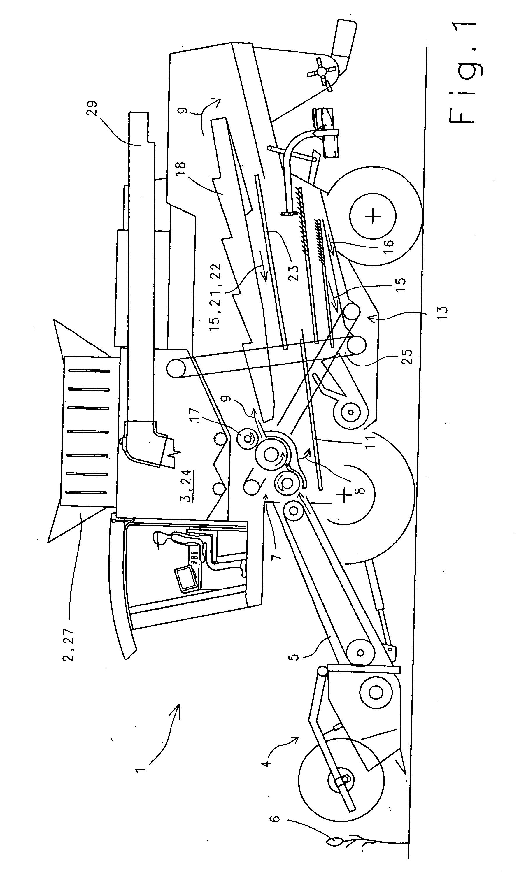
[0030]The combine harvester 1 shown in FIG. 1 includes an embodiment of the device 2 for increasing the volume of a grain tank 3. The combine harvester 1 is equipped with a header 4 on its front end, which is arranged on a feed rake 5. The combine harvester 1 takes the crop in with the header 4 and feeds it to the feed rake 5. The feed rake 5 conveys the crop 6 to a following threshing mechanism 7. The threshing mechanism 7 divides the crop 6 into a grain-chaff mixture 8 and a crop stream 9 comprising the stems or stalks. The grain-chaff mixture 8 is immediately fed to a cleaning device 13 by means of a grain pan 11, which separates the grain 15 from the non-grain components 16, i.e. the stalks and chaff components.

[0031]A beater 17 rotating counterclockwise is arranged downstream or behind the threshing mechanism 7. The beater 17 feeds the crop steam 9 comprising the threshed stalks to a straw walker rack 18. The straw walker rack 18 separates the grain 15, the short straw 21 and t...


PUM


Abstract

The device for increasing volume of a container (24) has extension elements (37, 38, 39, 40) pivotally mounted on an upper edge (31) of an upper opening (32) so as to form a cover at least partially closing the upper opening (32) when the extension elements (37, 38, 39, 40) are in flat closed positions and an enlarging extension (27) for the container when the extension elements are in raised filling positions, neighboring extension elements being pivotally connected with each other, and at least one driving pivoting device (53), which pivots or swings each extension element (37, 38, 39, 40) from its flat closed position into its raised filling position (47, 48, 49, 50) out beyond a vertical position thereof in a direction toward an exterior of the container, or from its raised filling position into its flat closed position.

Description

BACKGROUND OF THE INVENTION[0001]1. Field of the Invention[0002]The present invention relates to a device for increasing the volume or capacity of a container provided with an upper opening having an upper edge, which comprises a plurality of extension elements pivotally mounted on the upper edge of the opening, wherein the extension elements form a cover at least partially closing the opening when lying flat in a closing configuration and form an enlarging extension for the container in an erect filling configuration and neighboring extension elements are pivotally connected with each other.[0003]2. Description of the Related Art[0004]The grain tank of a combine harvester is provided with a grain tank extension, which comprises a plurality of side walls. The side walls are movable from a closed configuration into an opened configuration, and from the opened configuration to the closed configuration. During travel on a road the side walls are folded closed to form a cover to save sp...

Claims


Application Information

Patent Timeline
IPC IPC(8): A01F12/60A01D41/12B65D88/00B65D88/12
CPCA01D41/1226B65D88/126B65D88/123B65D88/005
Inventor ZEUNER, MAIKTHEISSING, GERHARDSPECHTEL, JOSEF
Owner CLAAS SELBSTFAHRENDE ERNTEMASCHINEN GMBH
Learn More