

Backlight apparatus, light source for backlight apparatus, and display apparatus using the same
a technology of backlight apparatus and light source, which is applied in the direction of luminescence, lighting and heating apparatus, instruments, etc., can solve the problems of not being able to experimentally produce various types of light sources, not and not being able to achieve the effect of improving the color reproducibility of display apparatuses
- Summary
- Abstract
- Description
- Claims
- Application Information
AI Technical Summary
Benefits of technology
Problems solved by technology
Method used
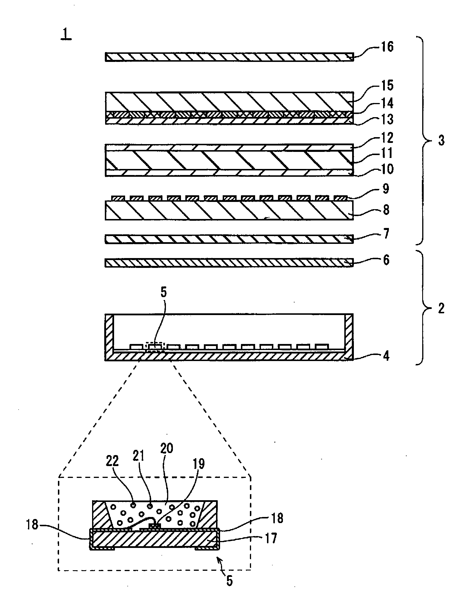
Image

Examples
examples
[0047]The following describes examples and comparative examples relating to the present embodiment.
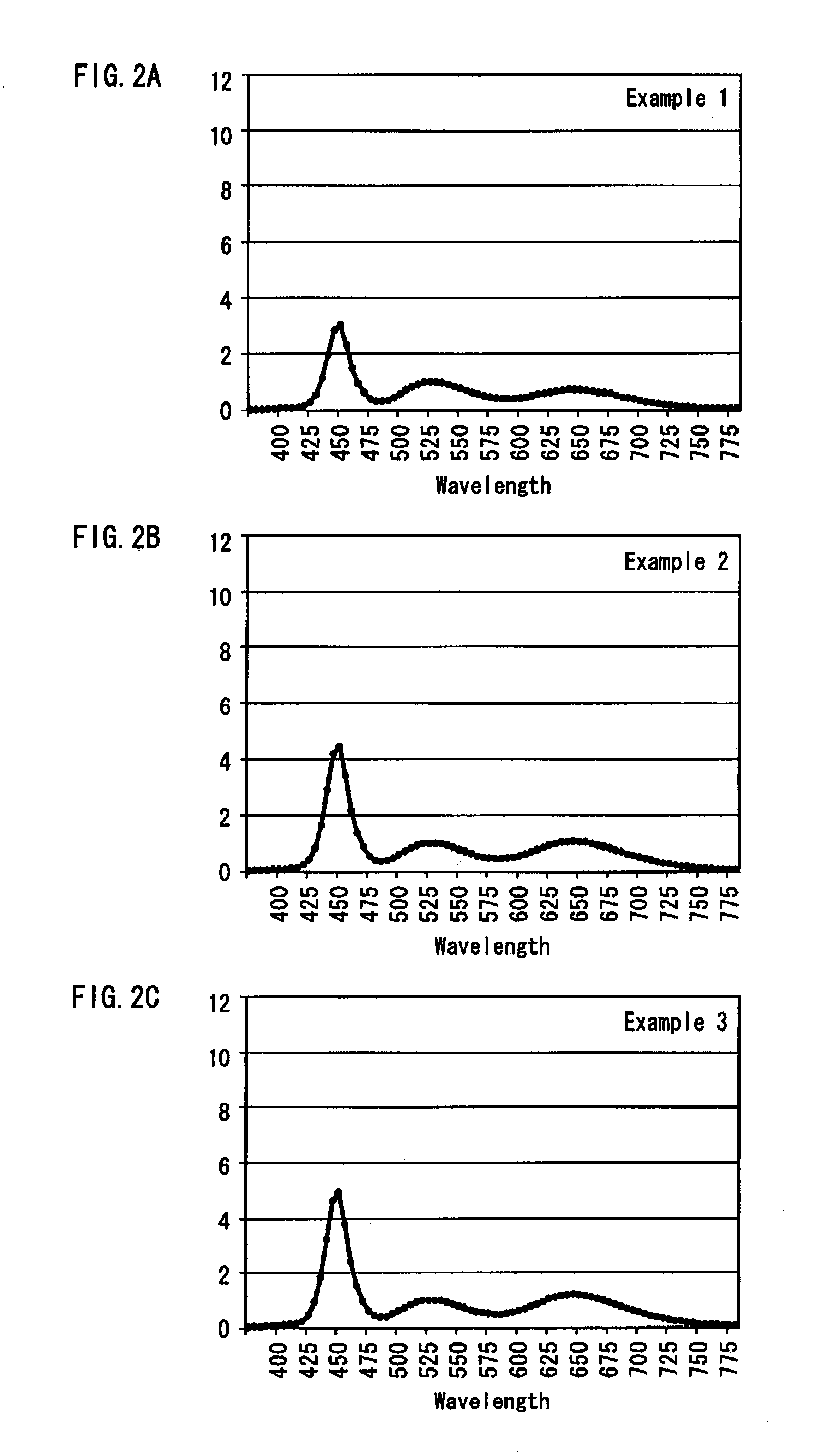
[0048]FIGS. 2A, 2B, and 2C show a light emission spectrum of a light source relating to Examples 1 to 3, respectively. FIGS. 3A, 3B, and 3C show a light emission spectrum of a light source relating to Examples 4 to 6, respectively. FIGS. 4A, 4B, 4C, and 4D show a light emission spectrum of a light source relating to Comparative Examples 1 to 4, respectively. These figures shows part of the simulations results obtained by the present inventors.
[0049]According to the Example 1, blue light has a peak at a wavelength of 450 [nm], green light has a peak at a wavelength of 525 [nm], and red light has a peak at a wavelength of 650 [nm]. According to the Example 1, the blue / green ratio in the light emission spectrum is 3.0. FIGS. 2A to 2C, 3A to 3C, and 4A to 4C show that the peak intensity of green light has a value of 1 in the Examples and the Comparative Examples, except for the Comparative...
PUM
| Property | Measurement | Unit |
|---|---|---|
| half width | aaaaa | aaaaa |
| half width | aaaaa | aaaaa |
| half width | aaaaa | aaaaa |
Abstract
Description
Claims
Application Information