Backlight device and flat display device using same

Inactive Publication Date: 2011-04-28
SHARP KK
View PDF6 Cites 37 Cited by
  • Summary
  • Abstract
  • Description
  • Claims
  • Application Information

AI Technical Summary

Benefits of technology

[0018]According to one aspect of the present invention, there is provided a backlight device that achieves a long life with a structure where a circuit board having a spot light source mounted thereon is unlikely to be

Problems solved by technology

Specifically, the operation failure at the time of assembly may cause bubbles between the FPC 102 and the side surface portion 103a of the lower chassis or may cause foreign matter contamination.
Ho

Method used


Image

  • Backlight device and flat display device using same
  • Backlight device and flat display device using same
  • Backlight device and flat display device using same

Examples


Example

[0027]An embodiment of a backlight device according to the present invention and a flat display device using such a backlight device will be described below with reference to the accompanying drawings. As an example of the flat display device, a liquid crystal display device in which liquid crystal is used in a display panel will be described below.

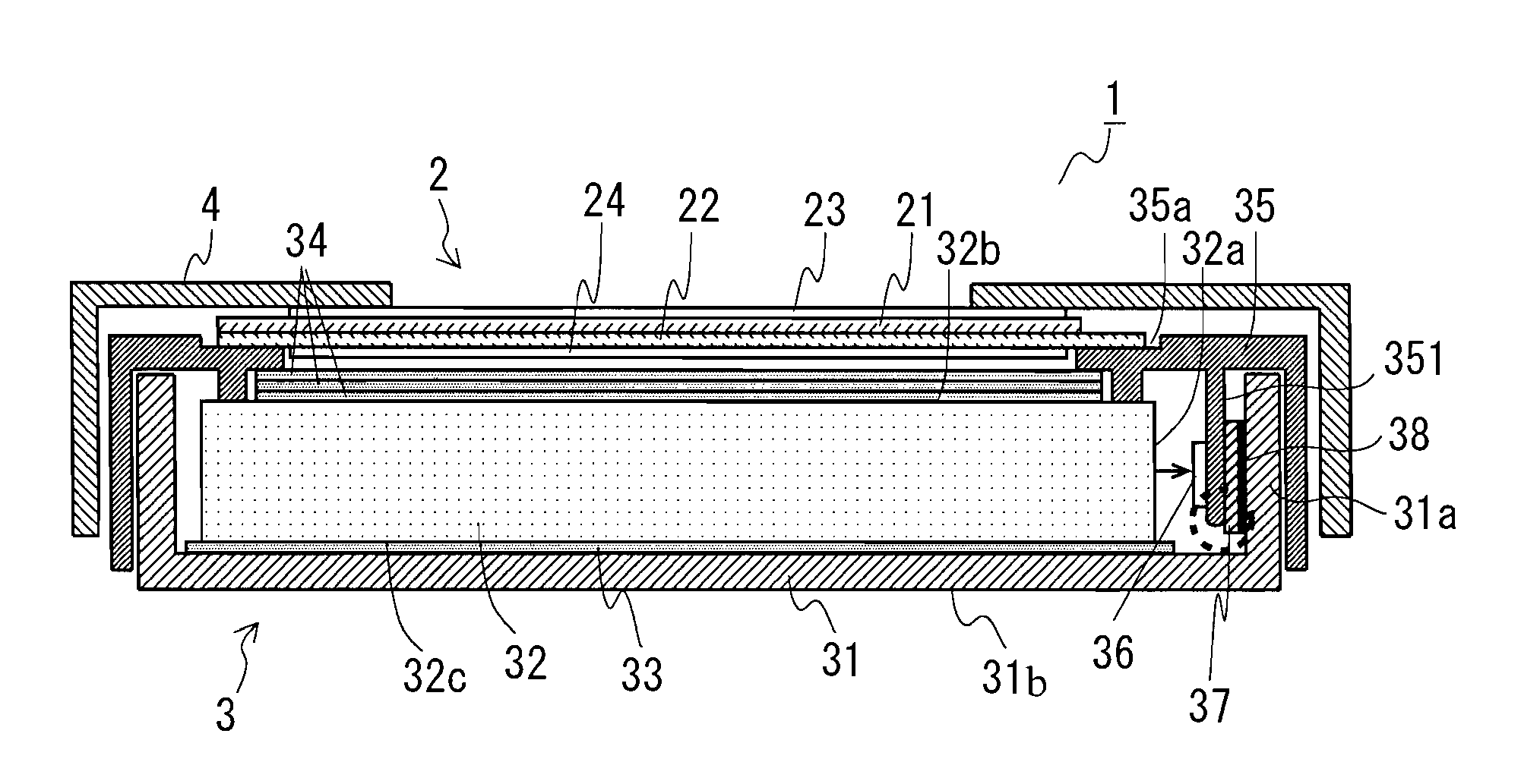
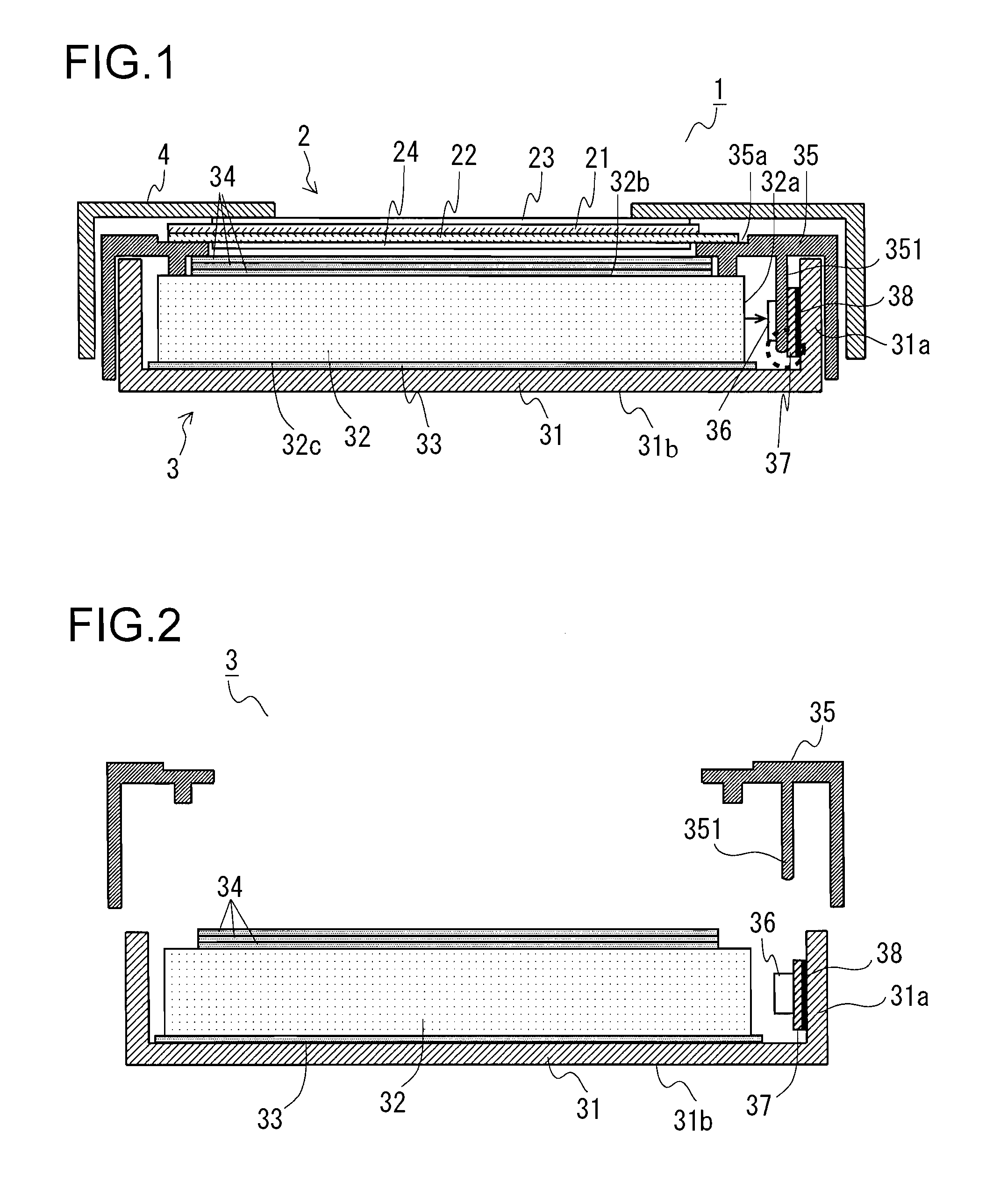
[0028]FIG. 1 is a schematic cross-sectional view showing the configuration of the liquid crystal display device of the present embodiment. The liquid crystal display device 1 of the present embodiment includes a liquid crystal panel 2 and a backlight device 3.

[0029]The liquid crystal panel 2 is formed by sealing in liquid crystal (not shown) between a pair of glass substrates 21 and 22 that are located apart from and opposite each other. The perimeter of the glass substrate 22 extends outward more than the glass substrate 21; a large number of electrode terminals (not shown) for applying voltage to pixel electrodes formed on the surface o...


PUM


Abstract

A backlight device (3) includes: a light guide plate (32); a chassis (31) on which the light guide plate (32) is mounted; a frame member (35) having the light guide plate (32) held between the chassis (31) and the frame member (35); a spot light source (36) arranged near a side surface of the light guide plate (32); a flexible printed circuit board (37) on which the spot light source (36) is mounted; and a heat dissipation plate (31a) (part of the chassis (31)) bonded through a double-faced adhesive (38) to the flexible printed circuit board (37). The frame member (35) is provided with a protrusion portion (351) that is in contact with the flexible printed circuit board (37) and that presses the flexible printed circuit board (37) onto the heat dissipation plate (31a), and a tip portion of the protrusion portion (351) is so tapered as to be located apart from the flexible printed circuit board (37).

Description

TECHNICAL FIELD[0001]The present invention relates to a backlight device that is used to illuminate a display panel from its back surface, and more particularly relates to a side-lit backlight device using a spot light source. The present invention also relates to a flat display device using such a backlight device.BACKGROUND ART[0002]In a display device, such as a liquid crystal display device, whose display panel itself does not emit light, a so-called backlight device illuminating the display panel from its back surface is generally arranged. Examples of the backlight device include a direct-lit backlight device, a side-lit backlight device and a planar light source backlight device; as display devices become thinner and lighter, the side-lit backlight devices are widely employed.[0003]In the side-lit backlight device, its light source is arranged near the side surface of a light guide plate, and light emitted from the light source enters the light guide plate from the side surfa...

Claims


Application Information

Patent Timeline
IPC IPC(8): F21V8/00
CPCG02B6/0068G02B6/0083G02B6/0085G02F2001/133322G02F1/133308G02F2001/133317G02B6/0088G02F1/133317G02F1/133322
Inventor HAMADA, TETSUYA
Owner SHARP KK
Why Eureka
Try Eureka