Golf club head

Active Publication Date: 2011-04-28
SUMITOMO RUBBER IND LTD
View PDF7 Cites 8 Cited by
  • Summary
  • Abstract
  • Description
  • Claims
  • Application Information

AI Technical Summary

Benefits of technology

[0007]Foreign matters such as mud and sand may enter into a face line during a rou

Problems solved by technology

These foreign matters reduce the performance of the face

Method used


Image

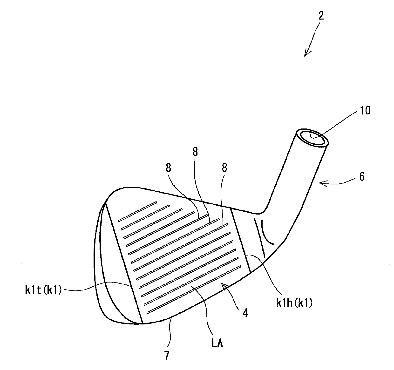
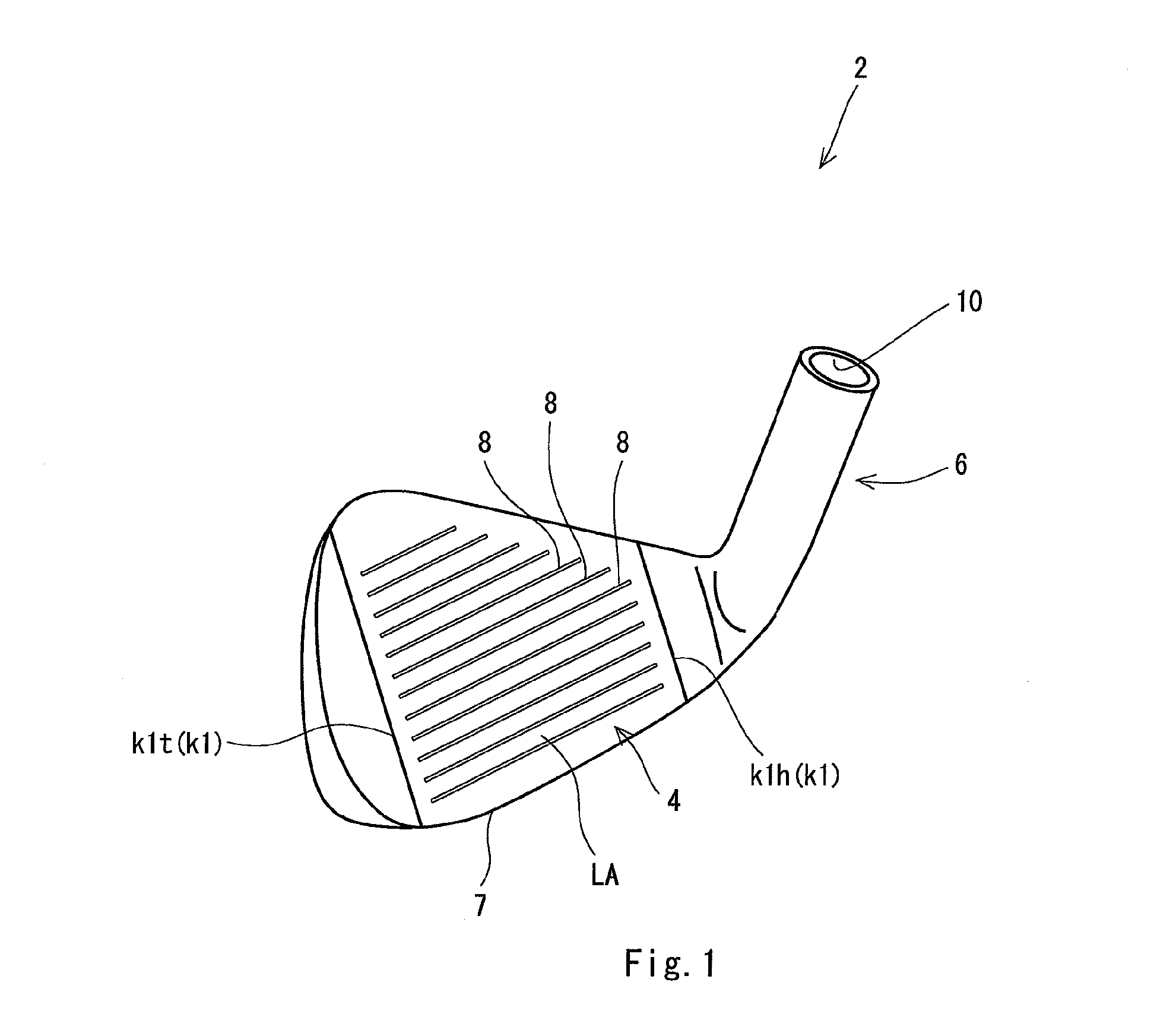
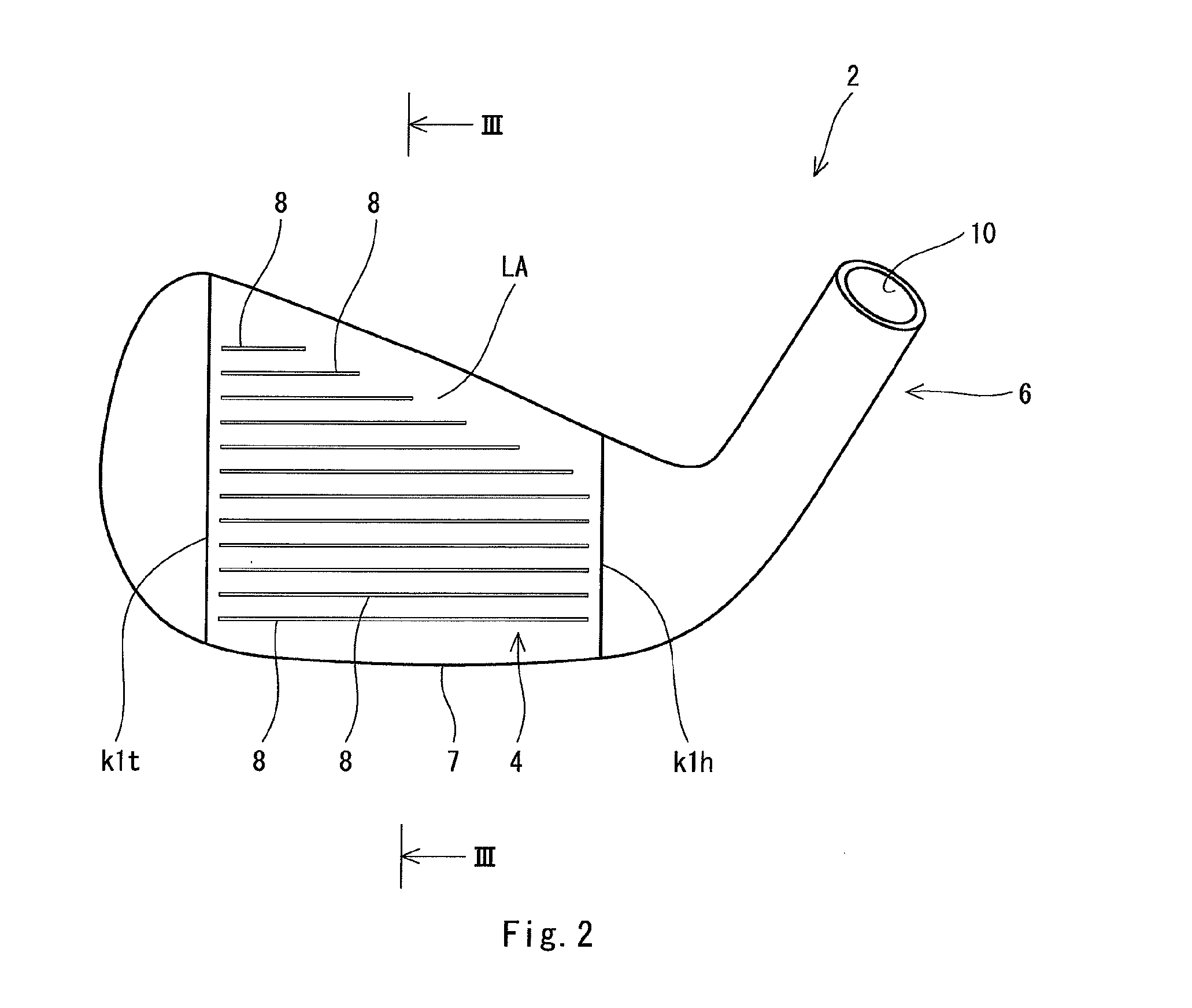
  • Golf club head
  • Golf club head
  • Golf club head

Examples


example 1

[0096]A head for a sand wedge of “XXIO5 IRON” (trade name) was used as a head having no face line formed thereon. The loft of the head was 58 degrees, and the lie angle was 63.5 degrees. The material thereof was SUS630, and the forming method was casting. The face line was formed on the head. In the method shown in FIG. 5, face lines were formed by cutting processing using a cutter. The material of the cutter was tungsten carbide. The sectional shape of the cutter was made the same as that of the face line. Therefore, the face lines were formed by one time cutting.

[0097]The number of the face lines provided on one head was 16. The pitch of the face lines was 3.2 (mm). The length of the longest face line was 55 (mm).

[0098]The face surface on which the face lines were formed was subjected to shot finishing. The shot finishing does not change the sectional shape of the face line substantially.

[0099]A shaft and a grip were mounted to the obtained head to obtain a golf club. “NS950 R” (t...

examples 2 to 6

[0100]Heads having face lines having different sectional shapes were obtained by changing the shape of a cutter. Heads and clubs of examples 2 to 6 were obtained in the same manner as in the example 1 except for the specifications shown in the following Table 1.

[0101]The sectional shapes of the examples 1 to 5 were set as shown in FIGS. 6 and 7. In the examples 1 to 5, the side face of the face line was occupied by only the first portion having the curvature radius R1 and the second portion having the curvature radius r1. On the other hand, the sectional shape of the example 6 was set as shown in FIGS. 3 and 4. The side face of the face line was occupied by only the portion having a curvature radius R1.


PUM


Abstract

A golf club head 2 includes a face line 8 having a depth of D1 (mm) and a land area LA. When a boundary point between the land area LA and the face line 8 in a section line of a surface of the face line 8 is defined as Pa; a point of which a depth is T1 (mm) is defined as Pb; and a curvature radius of the section line between the point Pa and the point Pb is defined as R1 (mm), the golf club head 2 satisfies the following formulae (1) and (2):
R1>T1  (1)
0.10≦T1≦0.5  (2)
Preferably, a ratio (R1/T1) is greater than 1.0 and is equal to or less than 3.0.

Description

[0001]The present application claims priority on Patent Application No. 2009-244280 filed in JAPAN on Oct. 23, 2009, the entire contents of which are hereby incorporated by reference.BACKGROUND OF THE INVENTION[0002]1. Field of the Invention[0003]The present invention relates to a golf club head having a face line.[0004]2. Description of the Related Art[0005]Face lines are formed on many golf club heads. The face lines can contribute to increase in the backspin rate of a ball.[0006]When the edge of the face line is sharpened, the backspin rate can be increased. However, in respect of the conformity to the rules, the sharp edge is not preferable. Therefore, a technique for applying a roundness and a chamfering to the edge is disclosed. Japanese Patent Application Laid-Open No. 2009-148538 (US2009 / 143165, US2009 / 143166) discloses a face line having an edge rounded so as to conform to the rules. Japanese Patent Application Laid-Open No. 2009-34393 (US2009 / 036228) discloses a face line ...

Claims


Application Information

Patent Timeline
IPC IPC(8): A63B53/04A63B102/32
CPCA63B53/04A63B53/047A63B53/0487A63B2209/023A63B2053/0416A63B2053/0445A63B2209/00A63B2053/0408A63B53/0445A63B53/0408A63B53/0416A63B60/00
Inventor SUGIMOTO, YASUSHI
Owner SUMITOMO RUBBER IND LTD
Why Eureka
Try Eureka