System and Method for Monitoring Ablation Size

a technology of ablation size and system, applied in the field of systems and methods, can solve the problems of unwanted heating of healthy tissue, large control requirements for non-invasive use of microwave energy, etc., and achieve the effect of preventing electrical shorting

Active Publication Date: 2011-04-28
TYCO HEALTHCARE GRP LP +1
View PDF26 Cites 60 Cited by
  • Summary
  • Abstract
  • Description
  • Claims
  • Application Information

AI Technical Summary

Benefits of technology

[0011]In one particular embodiment, the one or more modules include an ablation zone control module is in operative communication with a memory associated with the power source. The memory includes one or more data look-up tables including rectified dc voltages associated with the microwave antenna. The rectified dc voltages correspond to a radius of the ablation zone. The ablation control module is configured to instruct the power source to adjust the amount of microwave energy being delivered to the microwave antenna when a signal from radiation detection device is received at the ablation zone control module to create a uniform ablation zone of suitable proportion with minimal damage to adjacent tissue.
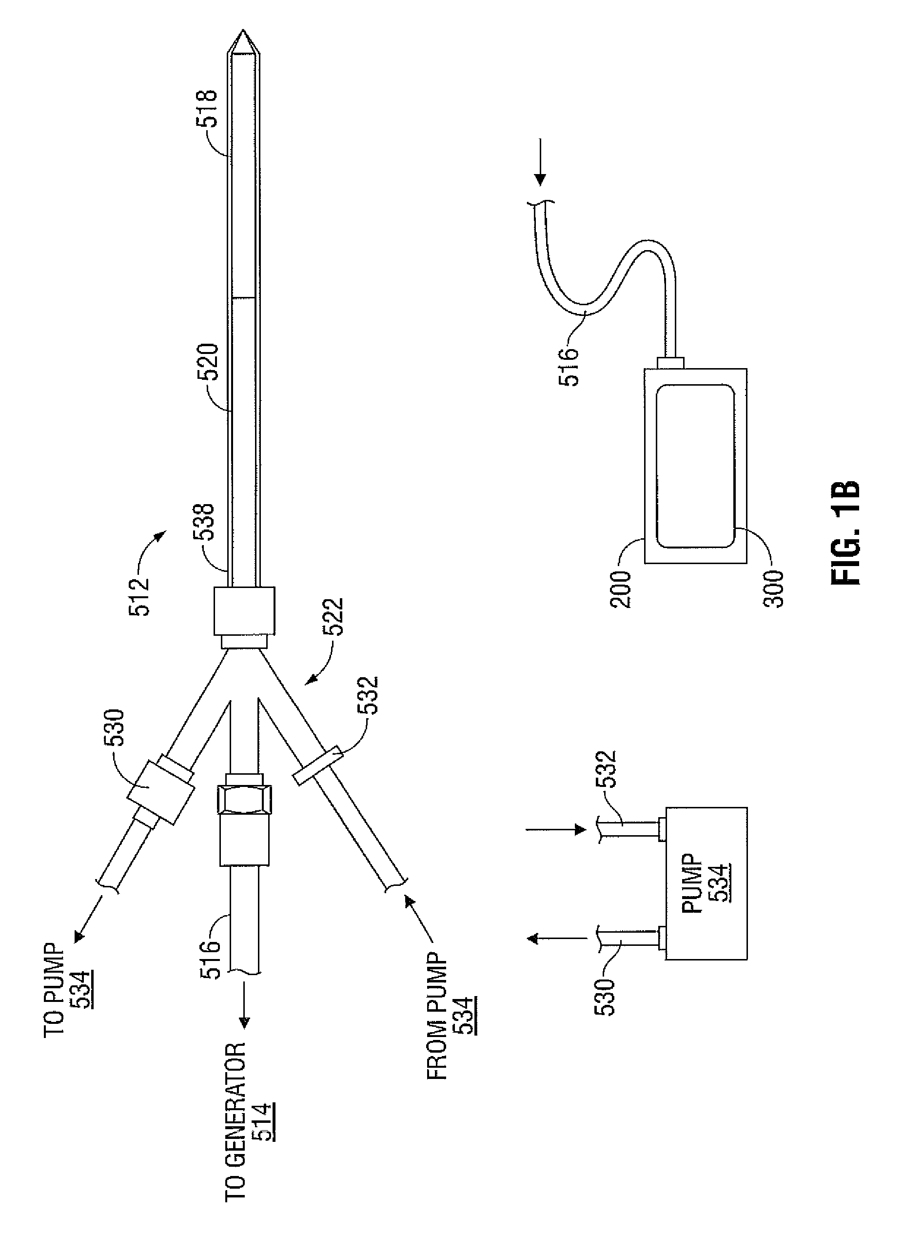
[0015]In an embodiment, a dielectric coating may be disposed between the shaft and the resonator coaxial feed to prevent electrical shorting between the resonator coaxial feed and the shaft.

Problems solved by technology

However, this non-invasive procedure may result in the unwanted heating of healthy tissue.
Thus, the non-invasive use of microwave energy requires a great deal of control.

Method used


Image

  • System and Method for Monitoring Ablation Size
  • System and Method for Monitoring Ablation Size
  • System and Method for Monitoring Ablation Size

Examples


Embodiment Construction

[0030]Embodiments of the presently disclosed system and method are described in detail with reference to the drawing figures wherein like reference numerals identify similar or identical elements. As used herein and as is traditional, the term “distal” refers to a portion that is furthest from the user and the term “proximal” refers to a portion of the microwave antenna that is closest to the user. In addition, terms such as “above,”“below,”“forward,”“rearward,” etc. refer to the orientation of the figures or the direction of components and are simply used for convenience of description.

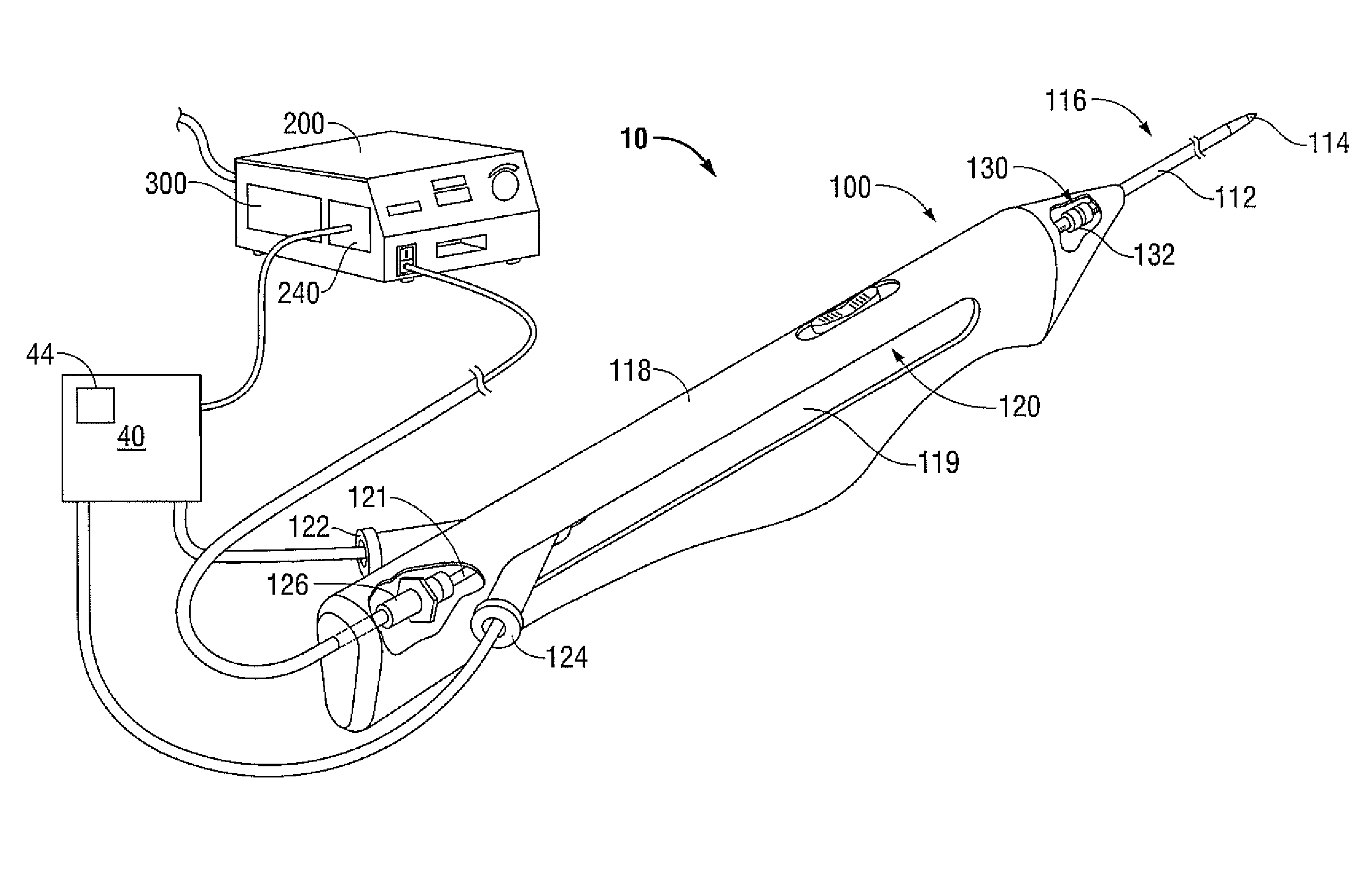
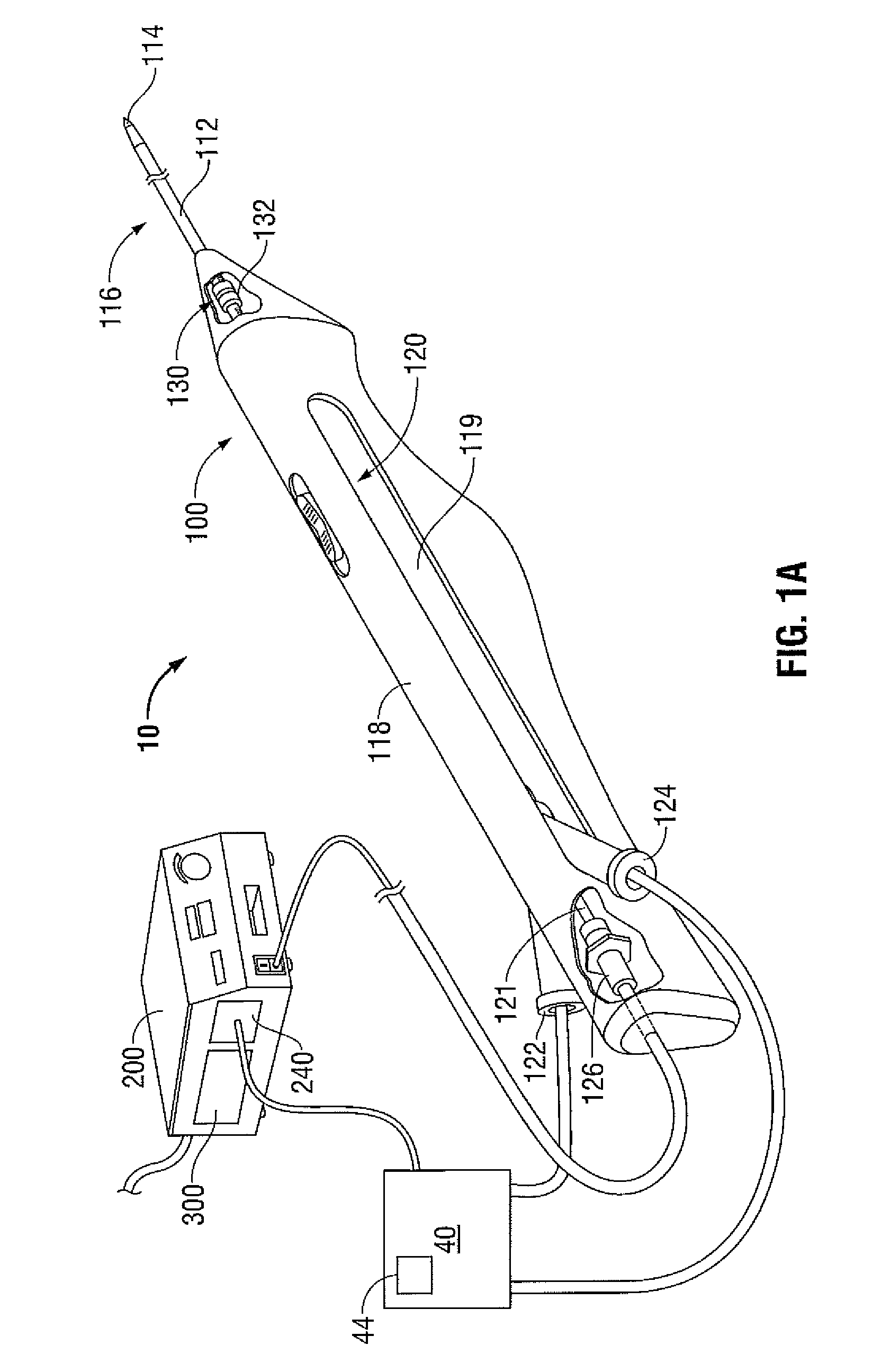
[0031]Referring now to FIG. 1A, a system for monitoring ablation size in accordance with an embodiment of the present disclosure is designated 10. The system 10 includes a microwave antenna 100 that is adapted to connect to an electrosurgical power source, e.g., an RF and / or microwave (MW) generator 200 that includes or is in operative communication with one or more controllers 300 and, in some insta...


PUM


Abstract

A system for monitoring ablation size is provided and includes a power source including a microprocessor for executing at least one control algorithm. A microwave antenna is configured to deliver microwave energy from the power source to tissue to form an ablation zone. A radiation detection device is operably disposed on the microwave antenna. The radiation detection device is configured to generate a voltage corresponding to a radius of the ablation zone, wherein the radiation detection device is in operative communication with at least one module associated with the power source. The at least one module triggers a signal when a predetermined threshold voltage is measured corresponding to the radius of the ablation zone.

Description

BACKGROUND[0001]1. Technical Field[0002]The present disclosure relates to systems and methods that may be used in tissue ablation procedures. More particularly, the present disclosure relates to systems and methods for monitoring ablation size during tissue ablation procedures in real-time.[0003]2. Background of Related Art[0004]In the treatment of diseases such as cancer, certain types of cancer cells have been found to denature at elevated temperatures (which are slightly lower than temperatures normally injurious to healthy cells). These types of treatments, known generally as hyperthermia therapy, typically utilize electromagnetic radiation to heat diseased cells to temperatures above 41° C. while maintaining adjacent healthy cells at lower temperatures where irreversible cell destruction will not occur. Procedures utilizing electromagnetic radiation to heat tissue may include ablation of the tissue.[0005]Microwave ablation procedures, e.g., such as those performed for menorrhag...

Claims


Application Information

Patent Timeline
Patent Type & Authority Applications(United States)
IPC IPC(8): A61B18/18
CPCA61B18/18A61B18/1815A61B2018/00023A61B2018/00577A61B2018/00642A61B2018/1861A61B2018/00684A61B2018/00702A61B2018/00779A61B2018/00892A61B2018/1892A61B2018/00666
Inventor BRANNAN, JOSEPH D.
Owner TYCO HEALTHCARE GRP LP
Why Eureka
Try Eureka