Transmission

a technology of transmission and transmission shaft, which is applied in the direction of couplings, fluid couplings, gearings, etc., can solve the problems of difficult assembly of hst, and achieve the effects of minimizing the width of the vehicle, good transmission balance, and good efficiency in power transmission

Active Publication Date: 2011-05-05
KANZAKI KOKYUKOKI MFG
View PDF5 Cites 28 Cited by
  • Summary
  • Abstract
  • Description
  • Claims
  • Application Information

AI Technical Summary

Benefits of technology

[0017]Further preferably, a charge pump is disposed on the outer surface of the second portion of the casing so as to be juxtaposed with the outer end of the output element. Therefore, the charge pump which must be externally attached to the casing of the transmission is disposed in the dead space defined by the step, thereby requiring no other space for arranging the charge pump, and thereby further compacting a layout of a vehicle power transmission system.
[0018]Preferably, the transmission further comprises an input element supported by the casing so as to be drivingly connected to the drive source and to drive the pump shaft. The input element, the pump shaft having the motor shaft member therearound, a rotary shaft constituting the reverser, and the output element are aligned on a spiral line centered on the input element when viewed in the axial direction of the pump shaft. Therefore, these elements and members are concentrated around the input element so as to compact the entire transmission while ensuring their good efficiency in power transmission. Further, these elements and members can be arranged around the input element to keep a good balance of the transmission.
[0019]Preferably, the transmission further comprises a pair of axles and a differential unit. The axles are extended in the axial direction of the pump shaft and are supported by the casing. The differential unit is disposed in the casing so as to transmit power outputted from the forward / backward traveling direction selecting unit to the axles. The differential unit includes a pair of differential yoke shafts, serving as the output element, extended in the axial direction of the pump shaft so as to be drivingly connected to the respective axles. The differential unit is entirely disposed between the axial ends of the pump shaft in the axial direction of the pump shaft. Therefore, the transmission can be provided as a transaxle supporting the pair of axles. The axial compactness of the differential unit minimizes the width of a vehicle between right and left wheels.
[0020]Further preferably, a pair of planetary gear units are disposed in the casing so as to be interposed between the respective differential yoke shafts of the differential unit and the respective axles. At least a part of each of the planetary gear units is disposed between the axial ends of the pump shaft in the axial direction of the pump shaft. Therefore, the planetary gear units can ensure a large speed-reduction ratio while they are disposed in the limited space between the axles, thereby requiring no additional gears for speed-reduction on the power train including the reverser and the differential unit.

Problems solved by technology

This HST is not easily assembled because the hydraulic pump and the hydraulic motor are attached to different places separately from each other.

Method used


Image

  • Transmission
  • Transmission
  • Transmission

Examples


Embodiment Construction

[0042]Various transmissions and various vehicles or vehicle-driving power transmission system equipped with the respective transmissions will be described with reference to the accompanying drawings. Hereinafter descriptions regarding directions are based on an assumption that arrows F shown in the drawings are directed forward.

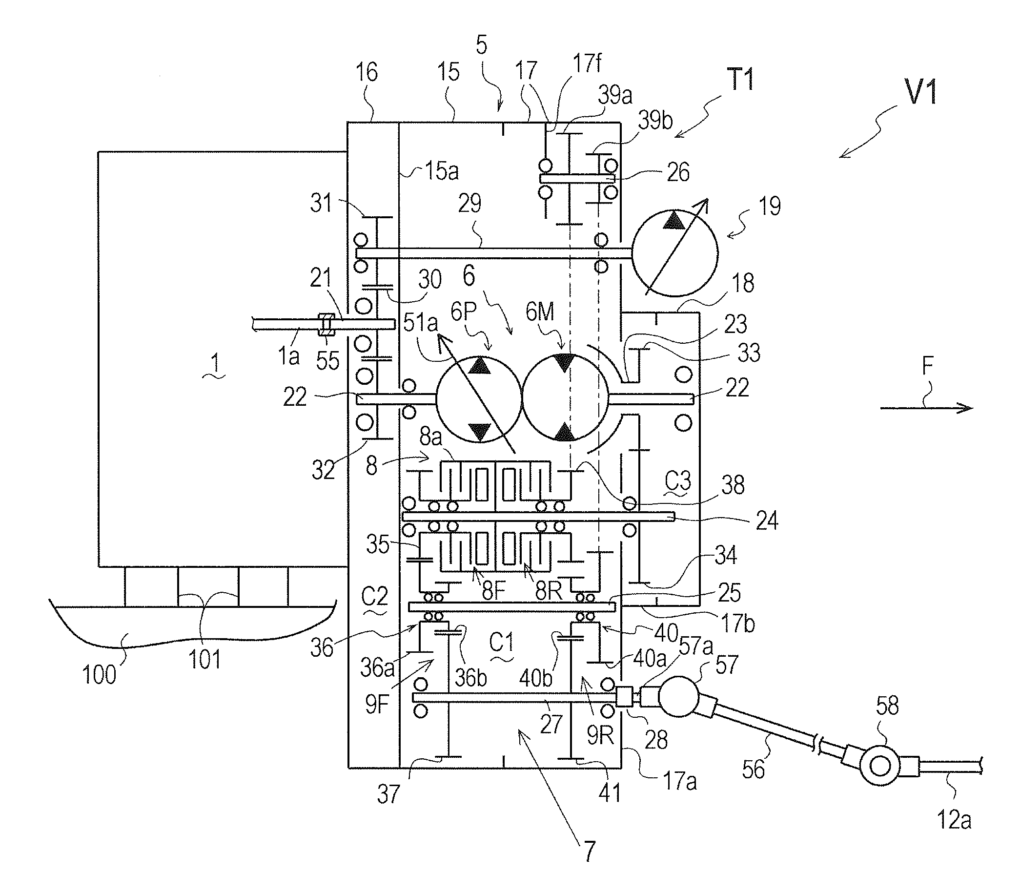
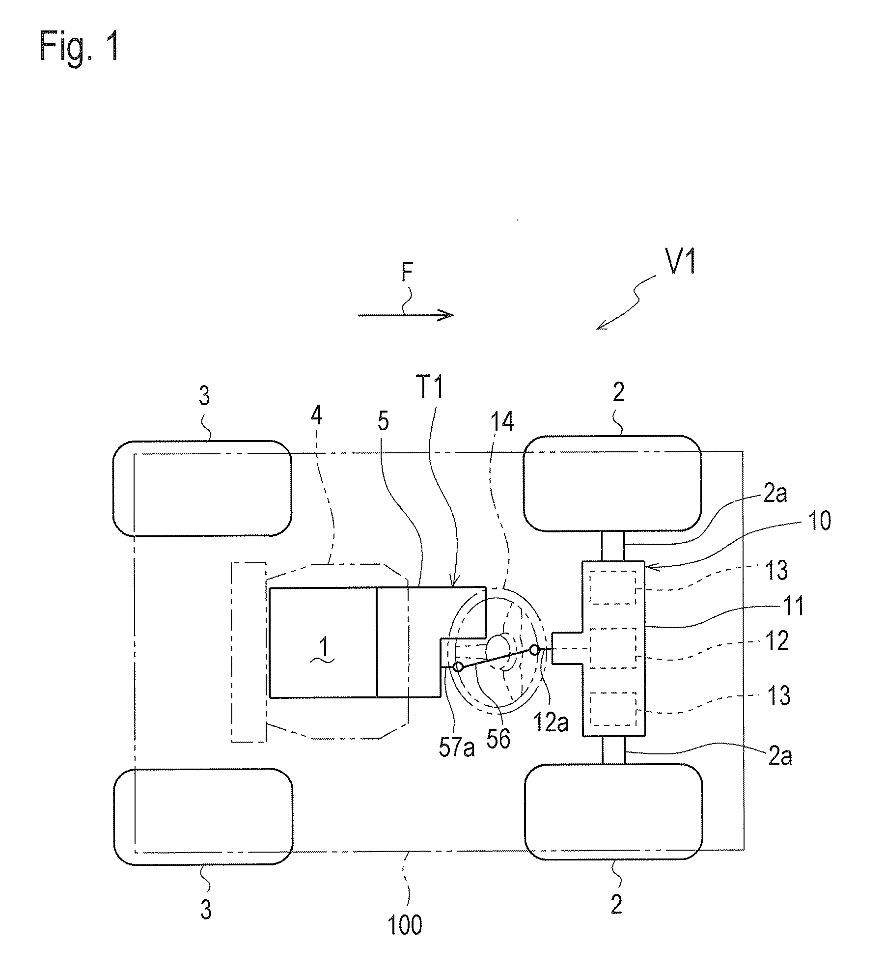
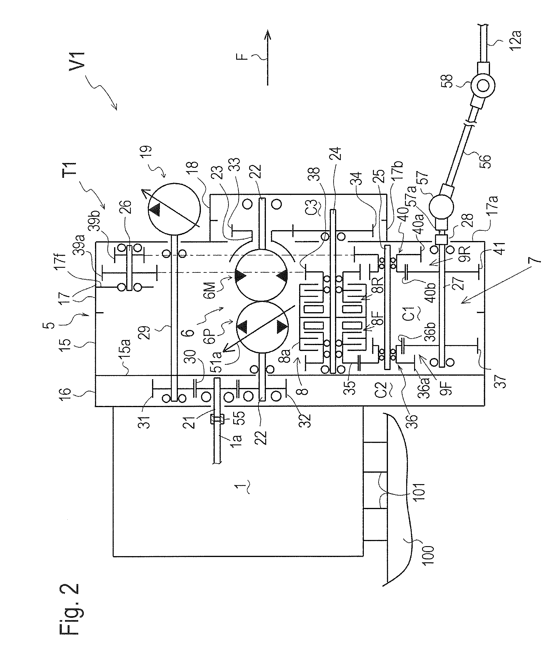
[0043]An embodiment shown in FIGS. 1 to 8 will be described. A vehicle V1 shown in FIG. 1 is a small-sized work vehicle such as a forklift or a utility vehicle. Vehicle V1 has a vehicle body 100, which is provided at a front portion thereof with right and left front wheels 2 serving as drive wheels, and at a rear portion thereof with laterally turnable right and left rear wheels 3 serving as steerable wheels. An engine 1 serving as a prime mover for driving a transmission T1 is mounted onto a lateral middle portion of vehicle body 100 in front of rear wheels 3 via vibration-isolating members 101 (see FIG. 2), such as rubbers. A casing 5 of integral transmissi...


PUM


Abstract

A transmission comprises a casing, an output element, a hydrostatic stepless transmission unit (HST) and a forward/backward traveling direction selecting unit (reverser). The output element is supported by the casing. The HST is disposed in the casing so as to be driven by a drive source disposed outside of the casing. The HST includes a pump shaft and a motor shaft member. The pump shaft is drivingly connected to the drive source. The motor shaft member is fitted around the pump shaft coaxially to the pump shaft so as to be rotatable relative to the pump shaft, thereby constituting a hydraulic pump and a hydraulic motor centered on the pump shaft and the motor shaft member. An axially distal end of the motor shaft member is disposed on the axially proximal side of an axially distal end of the pump shaft so that axial ends of the pump shaft are the axially most distal ends of the HST in the axial direction of the pump shaft. The reverser is disposed in the casing so as to transmit power outputted from the HST to the output element. The reverser includes a forward-traveling drive train, a backward-traveling drive train, and a clutch for selecting either the forward-traveling drive train or the backward traveling drive train to transmit the power outputted from the motor shaft member to the output element. The reverser and the output element are entirely disposed between the axial ends of the pump shaft in the axial direction of the pump shaft.

Description

BACKGROUND OF THE INVENTION[0001]1. Field of the Invention[0002]The present invention relates to a vehicle-driving power transmission provided with a hydrostatic stepless transmission (hereinafter, “HST”). Especially, the present invention relates to an integral transmission, which is defined as integrally including an HST and a forward / backward traveling direction selecting unit (reverser) in this application.[0003]2. Background Art[0004]As disclosed by JP H10-167687 A, there is a conventional forklift equipped with an HST serving as a transmission for transmitting power of an engine serving as a prime mover to drive wheels. In this forklift, a hydraulic pump is directly attached to the engine, a hydraulic motor is directly attached to a transaxle incorporating a differential mechanism, and the hydraulic pump and motor are fluidly connected to each other via hydraulic fluid pipes so as to constitute the HST. This HST is not easily assembled because the hydraulic pump and the hydrau...

Claims


Application Information

Patent Timeline
Patent Type & Authority Applications(United States)
IPC IPC(8): F16H61/438
CPCF16H47/02F16H2037/0886F16H47/04
Inventor ISHII, NORIHIROIWAKI, KOJI
Owner KANZAKI KOKYUKOKI MFG
Why Eureka
Try Eureka