Cable end retention clip assembly and method

a technology of cable end and assembly, which is applied in the direction of snap fasteners, buckles, mechanical devices, etc., can solve the problems of not being effective 100% of the time, not allowing as much design flexibility, etc., and achieves the effect of reducing the number of cable ends, facilitating and more robust installation/retention mechanisms, and robust cable end retention

Inactive Publication Date: 2011-05-05
AKEBONO BRAKE
View PDF33 Cites 11 Cited by
  • Summary
  • Abstract
  • Description
  • Claims
  • Application Information

AI Technical Summary

Benefits of technology

[0005]The present invention is directed to a unique solution to one or more of the problems discussed above. It is believed that the present invention provides a unique design and method of use of a cable end retention clip that allows for greater design flexibility in the components of the brake system and provides an easier and more robust installation / retention mechanism for the cable assembly. Particularly, the present invention allows for robust retention of the cable end when the cable assembly is not under a tensional load (e.g. control system of a brake or other system that uses such cable ends and assemblies).

Problems solved by technology

The products known in the art appear to serve this function to some extent, but do not allow for as much design flexibility as may be desirous or may require excessively tight manufacturing tolerances.
In one example, the product taught in U.S. Pat. No. 6,732,840, utilizes a stationary tab that protrudes from the housing assembly as a retention device, but is believed not to be effective 100% of the time.

Method used


Image

  • Cable end retention clip assembly and method
  • Cable end retention clip assembly and method
  • Cable end retention clip assembly and method

Examples


Embodiment Construction

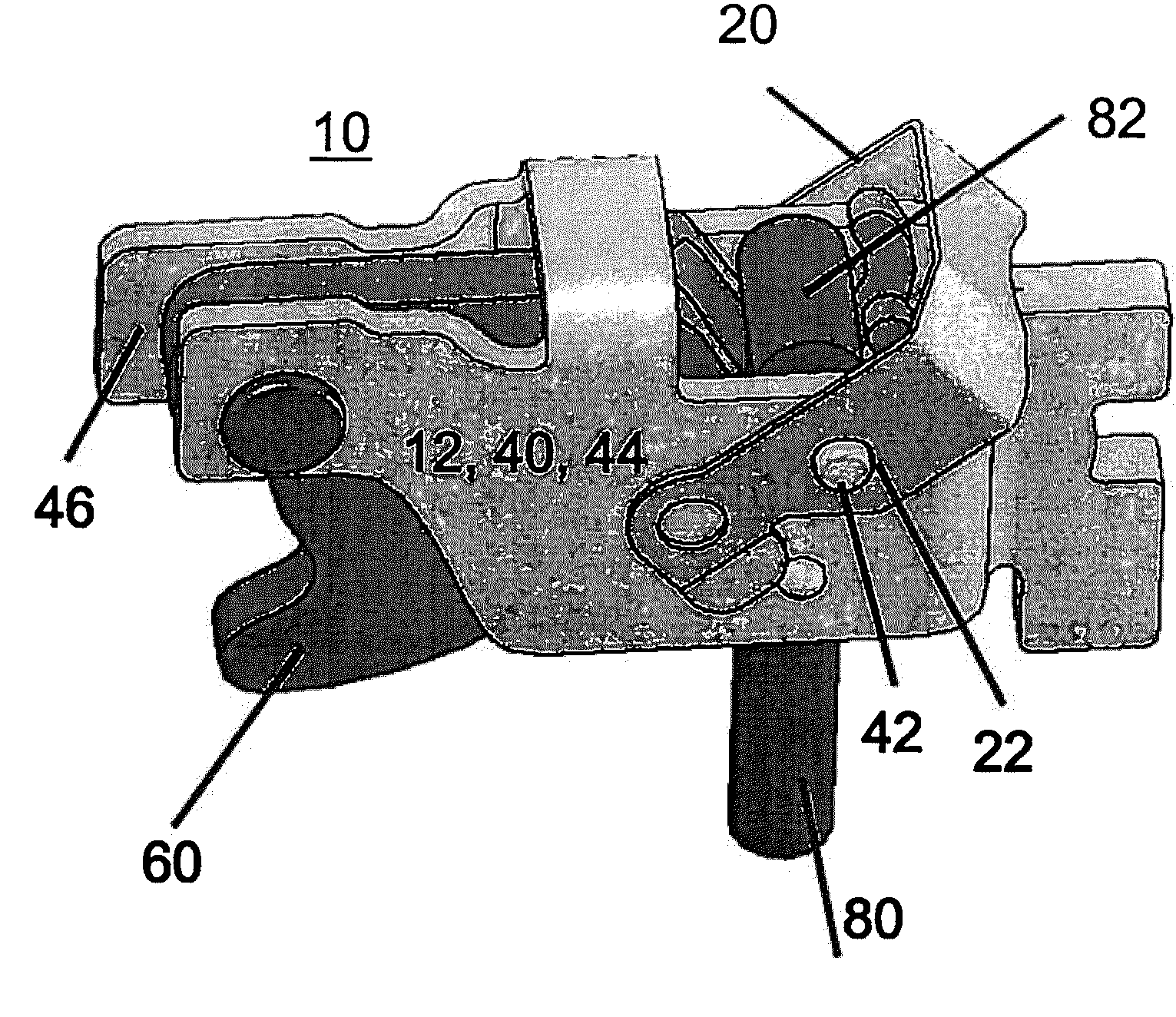
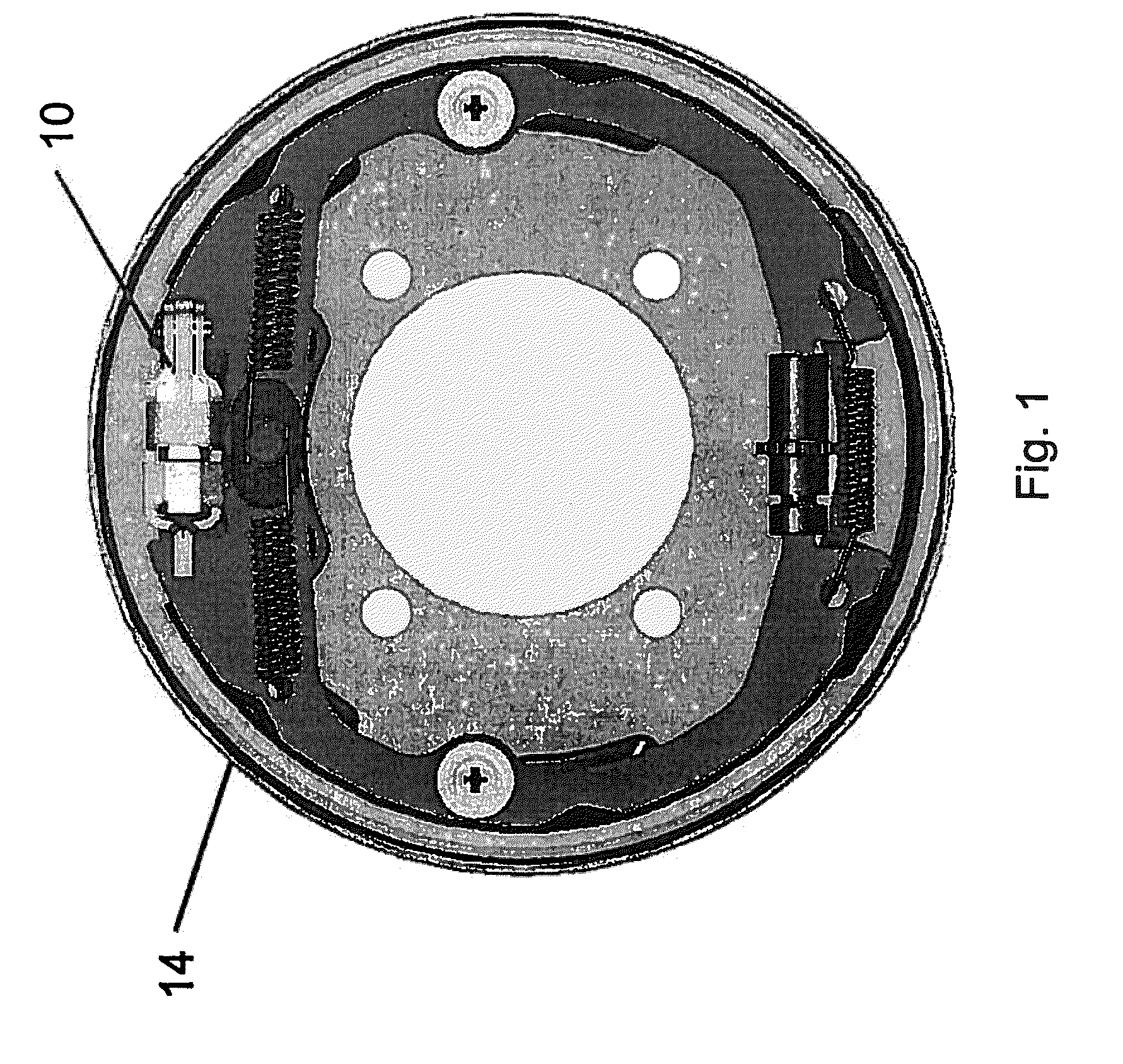
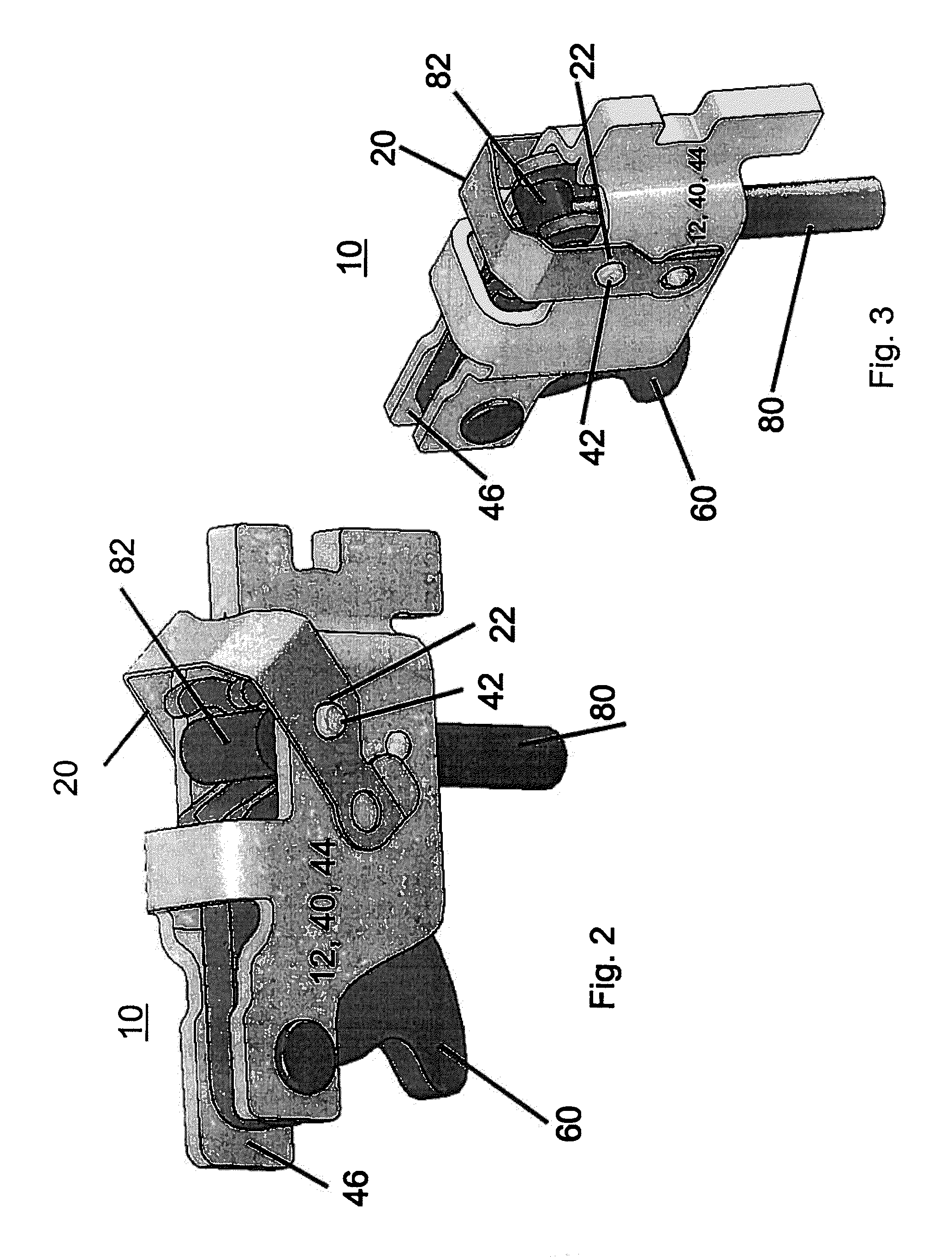
[0041]The present invention is directed to a unique solution for a cable end retention clip that allows for greater design flexibility (e.g. optimizing the system design) in the components of a brake system (e.g. drum brake assembly 14, FIG. 1). It is contemplated that the present invention may provide an easier and more robust installation / retention mechanism for a cable assembly within the greater brake system, principally in the cases where the cable assembly is not under a tensional load when it is first assembled. The examples provided in this application will focus on the installation / retention mechanism in an expander component assembly of the brake system (e.g. an expander component assembly that is used in the parking brake function), although use of this inventive clipping system in other areas in the brake system is contemplated. It is contemplated that all of the components discussed below may be constructed of any number of materials that are appropriate to be used in t...


PUM


Abstract

The present invention is premised upon a clip and housing plate assembly capable of (“to accommodate”) loading, unloading and retaining a cable end within the housing plate assembly. Of particular interest is the clip and housing plate assembly used in a drum brake assembly and where the cable end is part of a cable assembly for a parking brake. The clip and housing plate assembly having clip member and a housing plate member and wherein the clip member is generally disposed outside an outer surface (or inside an inside surface) of the of the housing plate member and rotatably connected thereto.

Description

CLAIM OF PRIORITY[0001]The present application claims the benefit of the filing date of U.S. Provisional Application Nos. 61 / 258265 filed on 9 Nov. 2009, the contents of which are hereby incorporated by reference in their entirety.FIELD OF THE INVENTION[0002]The present invention relates to a cable end retention clip assembly and method of using such, more particularly to a retention clip and method for a control cable of a brake system of a vehicle.BACKGROUND[0003]Efforts to improve the state of the art in the area of brake assemblies continue to elicit considerable inventive energy. Of particular interest is the desire to optimize the design of various brake assembly components and the system as a whole. Optimizing the system design such that it can be relatively low mass, having efficient use of materials, and allowing generous manufacturing tolerances, all without giving up on the requirements of having a robust system that meets desired performance requirements. One design elem...

Claims


Application Information

Patent Timeline
Patent Type & Authority Applications(United States)
IPC IPC(8): F16D65/30A44B99/00F16D65/28
CPCF16D51/22Y10T24/39F16D2125/62
Inventor NARAYANAN V., LAKSHMILAYTON, CHARLES T.
Owner AKEBONO BRAKE
Why Eureka
Try Eureka