Ac-dc converter, method of controlling the same, motor driver, compressor driver, air-conditioner, and heat pump type water heater

a technology of ac-dc converter and ac-dc converter, which is applied in the direction of electronic commutation motor control, motor/generator/converter stopper, dynamo-electric converter control, etc., can solve the problem of imbalanced voltage of capacitors connected in series, and achieve the effect of reducing cost and putting into practicable us

Active Publication Date: 2011-05-05
MITSUBISHI ELECTRIC CORP
View PDF9 Cites 32 Cited by
  • Summary
  • Abstract
  • Description
  • Claims
  • Application Information

AI Technical Summary

Benefits of technology

[0030]According to an AC to DC converter of the present invention, by controlling an ON / OFF timing of first and second switching means, it is possible to output a three-level converter voltage while performing time-width control to output a sinusoidal converter voltage.
[0031]Thus, the current flowing through the reactor can be controlled to be sinusoidal, achieving the small-sized reactor.
[0032]Since a three-level converter voltage is output while controlling time-width, switching operation can be performed at a low frequency and the converter can be put into practical use inexpensively by reducing cost for high-frequency noise countermeasures.

Problems solved by technology

As a technique whose problem is that “in a configuration where a full-wave rectification circuit constituted by a single-phase AC power unit and diodes, a reactor, a capacitor series circuit, a bi-directional switch, and a load are connected, when making an AC input current to have a high power factor by switching the bi-directional switch, the voltage of the capacitor connected in series becomes imbalanced during a half-cycle period”, the technique is proposed such that “in a configuration such that a reactor is connected with one of the AC input terminals of a full-wave rectification circuit composed of a single-phase AC power unit and diodes, a capacitor series circuit is connected between the DC output of the full-wave rectification circuit, bi-directional switches 10 and 11 are connected between internal connection points of the capacitor series circuit and each AC input of the full-wave rectification circuit, and a load 14 is connected in parallel with the capacitor series circuit, respectively, voltages of the capacitors 12 and 13 connected in series are detected and bi-directional switches 10 and 11 are on-off controlled at high frequency in such a way that the voltages become even” (Patent Literature 8)

Method used


Image

  • Ac-dc converter, method of controlling the same, motor driver, compressor driver, air-conditioner, and heat pump type water heater
  • Ac-dc converter, method of controlling the same, motor driver, compressor driver, air-conditioner, and heat pump type water heater
  • Ac-dc converter, method of controlling the same, motor driver, compressor driver, air-conditioner, and heat pump type water heater

Examples


example 1

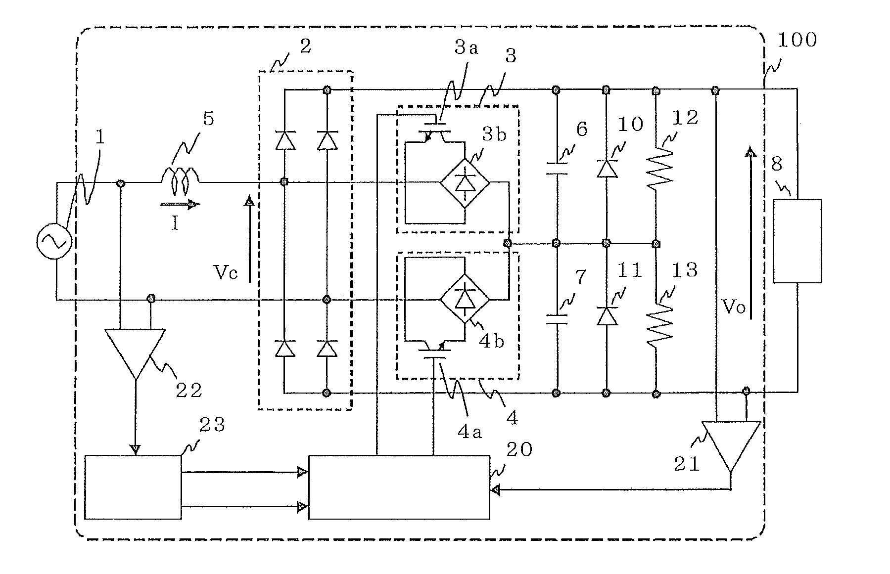
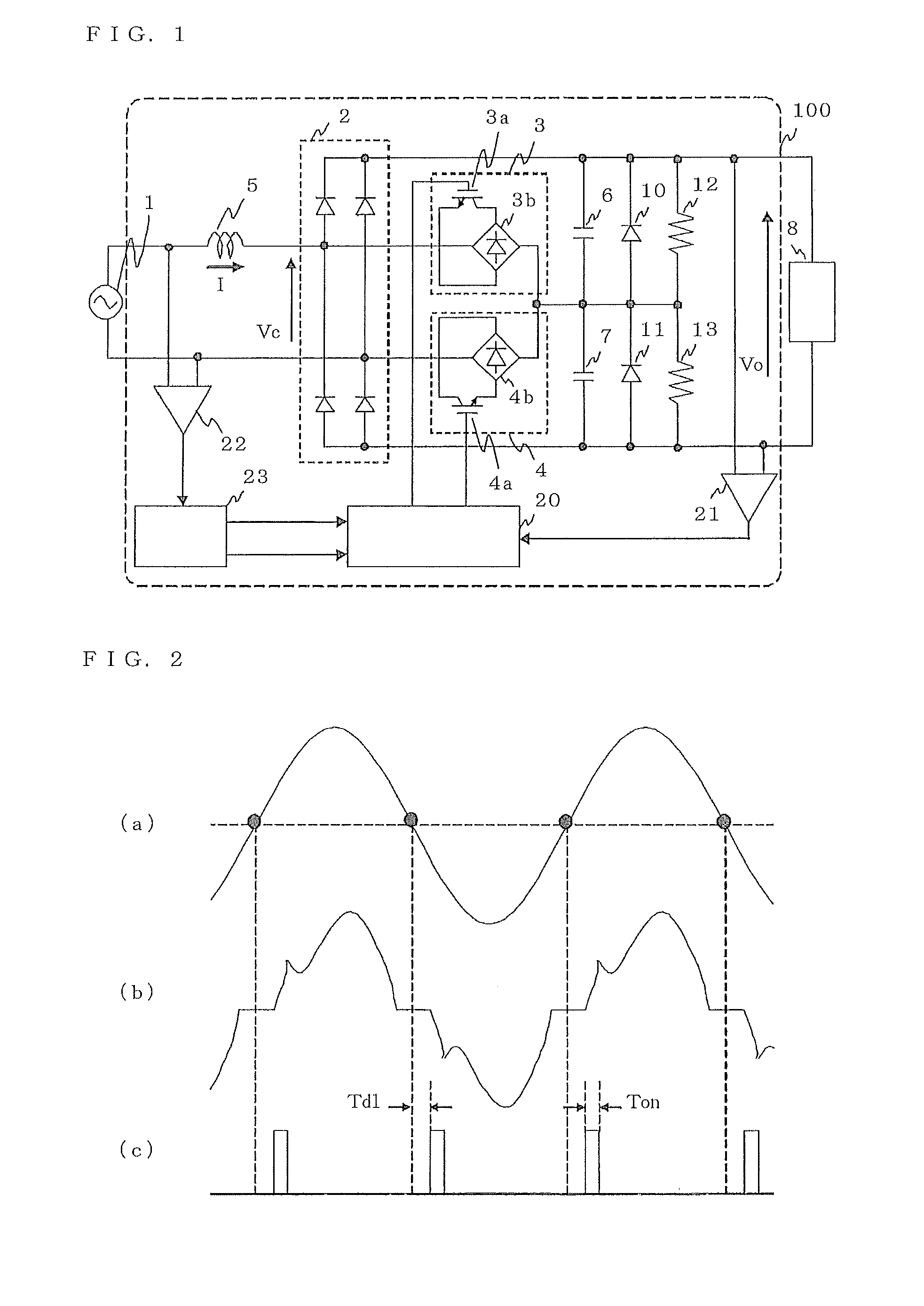
[0071]FIG. 1 is a circuit diagram of an AC to DC converter 100 according to Embodiment 1. The circuit of FIG. 1 includes an AC source 1, a rectifier 2, first switching means 3, second switching means 4, a reactor 5, a first capacitor 6, a second capacitor 7, a DC load 8, a first diode 10, a second diode 11, a first resistor 12, a

[0072]second resistor 13, control means 20, a first voltage detector 21, a second voltage detector 22, and an effective value operation portion 23.

[0073]The AC source 1 supplies AC power from outside of the AC to DC converter 100. The rectifier 2 rectifies the AC power of the AC source 1 to the DC power. One end of the first switching means 3 is connected with one of the input terminals of the rectifier 2, and the other end with the connection point between the first capacitor 6 and the second capacitor 7. One end of the second switching means 4 is connected with the other of the input terminals of the rectifier 2, and the other end with the connection point...

embodiment 2

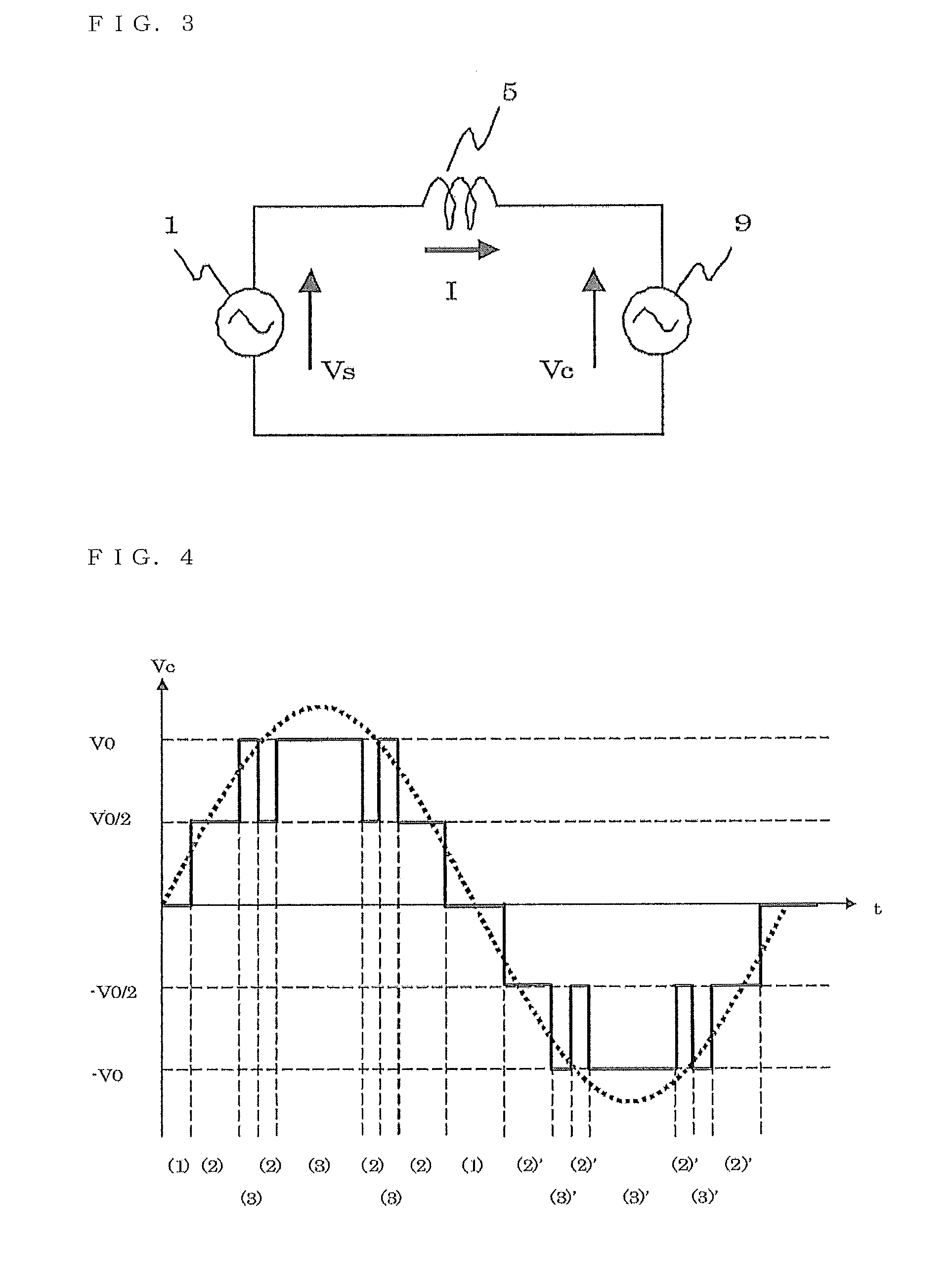
[0147]In Embodiment 1, it is explained that by sinusoidally outputting the converter voltage Vc, the input voltage is made to be almost sinusoidal and harmonics can be suppressed.

[0148]In Embodiment 2, descriptions will be given to the control of the value of the output DC voltage V0 of the AC to DC converter 100. Circuit configuration of the AC to DC converter 100 is the same as Embodiment 1.

[0149]Under the conditions of FIGS. 5(b), 5(c), 5(f), and 5(g) explained in Embodiment 1, the connection point of the first capacitor 6 and the second capacitor 7 is connected with one end of the AC source 1. Therefore, the same circuit configuration as the voltage doubler rectification is formed.

[0150]Like those conditions, when only either of the switching means is turned on, in other words, by properly controlling the ratio to be Vc=V0 / 2, it is possible to control the value of the output DC voltage V0 to be equal to or larger than a DC voltage value obtained by the full-wave rectification.

[0...

embodiment 3

[0217]FIG. 10 is a circuit diagram of the AC to DC converter 100 according to Embodiment 3.

[0218]In the circuit of FIG. 10, configuration of the switching means is changed from the circuit configuration in FIG. 1. Other configurations are the same as FIG. 1.

[0219]In the circuit of FIG. 10, IGBT 3a and 4a, which are a unidirectional switching element, can perform an equivalent operation to the bidirectional switching means explained in FIG. 1 through a function of the diode rectifier 14.

[0220]Accordingly, in the circuit configuration of FIG. 10, the same control operation can be performed as those explained in Embodiments 1 and 2.

[0221]Because of the circuit configuration like FIG. 10, when IGBT 3a and 4a perform ON operation, the number of diodes in which current flow becomes half of FIG. 1. Therefore, conduction loss of the diode can be made to be half of the circuit configuration of FIG. 1.

[0222]Thereby, conversion efficiency of the AC to DC converter 100 can be improved.


PUM


Abstract

A rectifier connected with an AC source through a reactor, a plurality of capacitors connected in series between output terminals of the rectifier, first switching means connected between one input terminal of the rectifier and a connection point of a plurality of capacitors, second switching means connected between the other input terminal of the rectifier and the connection point of a plurality of capacitors, and a plurality of diodes connected with the plurality of capacitors in inverse-parallel are provided.

Description

TECHNICAL FIELD[0001]The present invention relates to an apparatus that converts AC to DC.BACKGROUND ART[0002]Conventionally, as a technique intended “to obtain a DC power unit that reduces harmonic components of an input current to optimally improve power factor”, the technique is proposed such that “when an AC voltage of an AC source passes at a zero point, switching means is made to perform a closing operation after a preset first delay time from the pass time and switching means is made to perform an opening operation after a preset second delay time from the pass time. (Patent Literature 1)[0003]Further, as a technique intended “to lower a processing speed in control, to improve power factor, to reduce harmonics, and to achieve low cost by reducing the frequency of switching to achieve a minimal switching frequency”, the technique is proposed such that “there are provided a rectification circuit 2 that rectifies the voltage of an AC source 1, a smoothing capacitor 4 that smooth...

Claims


Application Information

Patent Timeline
Patent Type & Authority Applications(United States)
IPC IPC(8): H02P27/00H02M7/219H02M7/12H02P23/26H02P27/06
CPCH02M1/126H02M1/4233H02P6/001H02M1/4208Y02B70/126H02P6/34Y02B70/10
Inventor SHINOMOTO, YOSUKETAKAHARA, HIDEKIHANDA, MASATOTANIKAWA, MAKOTOKASHIMA, MITSUO
Owner MITSUBISHI ELECTRIC CORP
Why Eureka
Try Eureka