Amplifier circuit with overshoot suppression

an amplifier circuit and suppression scheme technology, applied in the field of amplifier circuits, can solve problems such as abnormal operation of back circuits to receive signals, unstable signals, overshoots in output signals, etc., and achieve the effect of rapid smoothing of output signals

Active Publication Date: 2011-05-05
NOVATEK MICROELECTRONICS CORP
View PDF3 Cites 8 Cited by
  • Summary
  • Abstract
  • Description
  • Claims
  • Application Information

AI Technical Summary

Benefits of technology

Based on the above, in the amplifier circuit of the embodiment of the invention, the diode device is used to detect the voltage difference between the output end and the input end of the output amplifier. When the voltage difference between the output and the input ends of the output amplifier is greater then the barrier voltage of the diode device, the diode device is turned on, so that the output end of the output amplifier is coupled to the input end of the output amplifier. Accordingly, in the transient state, it can rapidly smooth the output signal with overshoot. In the steady state, because the voltage difference between the output and the input ends of the output amplifier is less then the barrier voltage of the diode device, the diode device is cut off to maintain the normal operation of the operational amplifier.

Problems solved by technology

For the conventional amplifier, when it outputs the output signal, the overshoot may occur in the output signal during the dynamic operation due to the phase margin, the insufficient area, and so on.
When the signal is outputted, it will cause the signal to be unstable.
Accordingly, the back circuit to receive the signal may operate abnormally, and even the circuit is burned out.

Method used


Image

  • Amplifier circuit with overshoot suppression
  • Amplifier circuit with overshoot suppression
  • Amplifier circuit with overshoot suppression

Examples


first embodiment

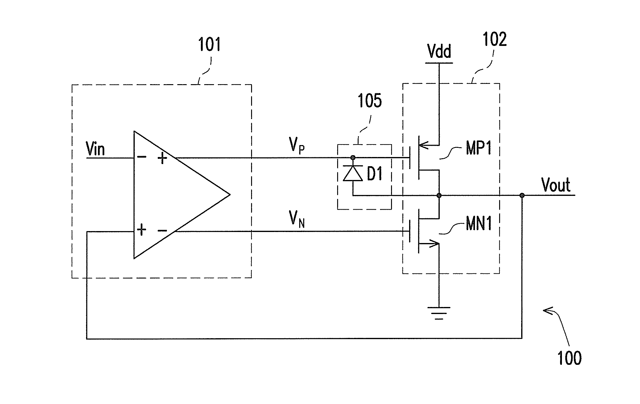
FIG. 1 is a schematic view of an amplifier circuit with an overshoot suppress scheme according to the invention. Referring to FIG. 1, the amplifier circuit 100 includes an input amplifier 101, an output amplifier 102, and a first diode device 105. In the present embodiment, the input amplifier 101 has a first input end, a second input end, and a differential output pair. The output amplifier 102 has a first input end, a second input end, and an output end. The first and the second input ends of the output amplifier 102 are respectively coupled to the differential output pair of the input amplifier 101, and the output end of the output amplifier 102 provides the output voltage Vout.

A first end of the first diode device 105 is coupled to the output end of the output amplifier 102, and a second end of the first diode device 105 is coupled to the first input end of the output amplifier 102. When a voltage difference between the output end of the output amplifier 102 and the first input ...

third embodiment

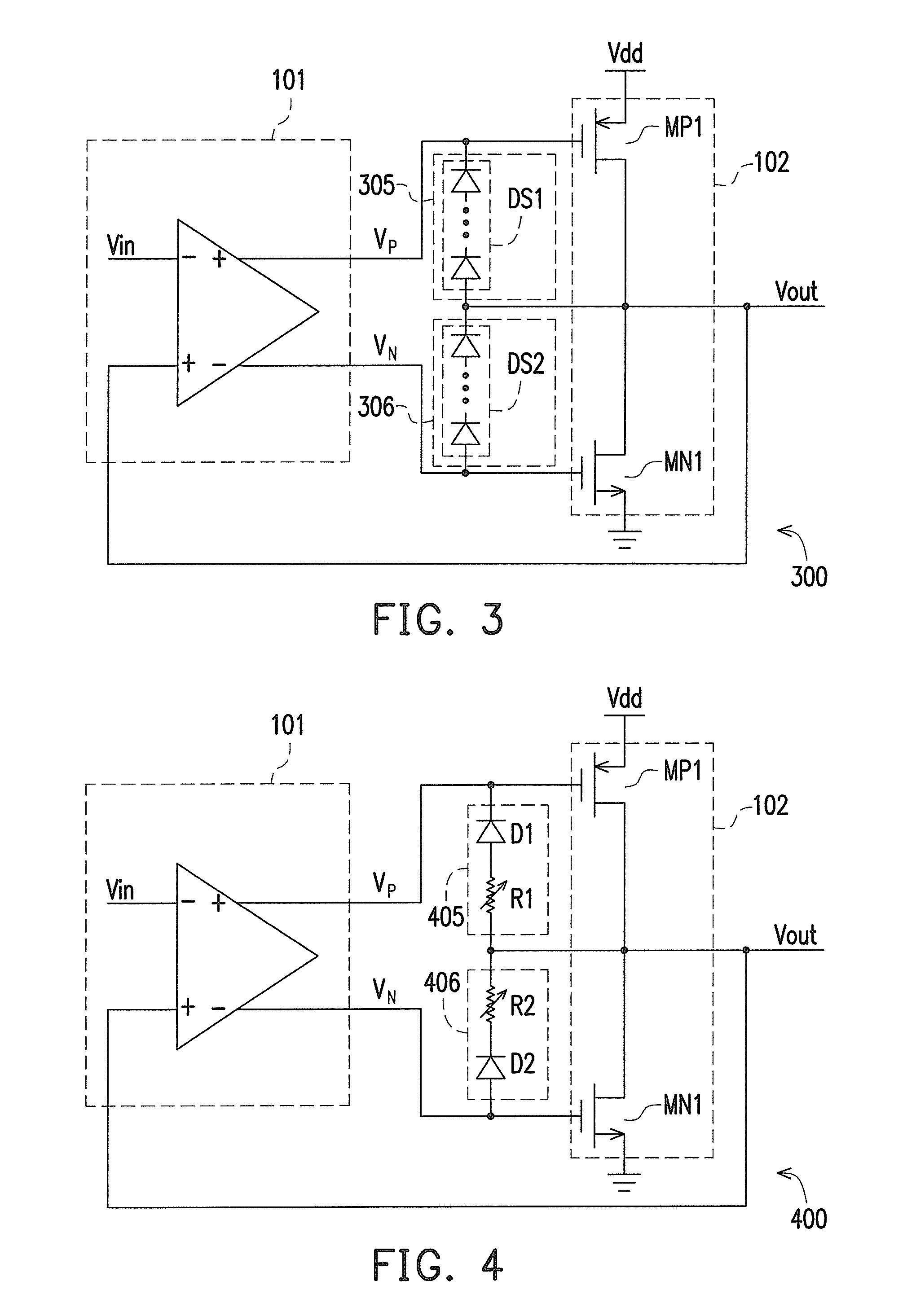
Herein, another embodiment of the invention is provided. FIG. 3 is a schematic view of an amplifier circuit with the overshoot suppress scheme according to the invention. Referring to FIG. 3, the amplifier circuit 300 with the overshoot suppress scheme is integrated by the amplifier circuits 100 and 200. The implementation of the amplifier circuit 300 can refer to the related illustration of the amplifier circuits 100 and 200. The amplifier circuit 300 has the first diode device 305 and the second diode device 306. The first end of the first diode device 305 is coupled to the output end of the output amplifier 102, and the second end of the first diode device 305 is coupled to the first input end of the output amplifier 102. The first end of the second diode device 306 is coupled to the output end of the output amplifier 102, and the second end of the second diode device 306 is coupled to the second input end of the output amplifier 102.

In the present embodiment, the first diode dev...

fourth embodiment

Those who use the present embodiment can add a variable resistor to the diode device to increase the barrier voltage of the diode device as shown in FIG. 4. FIG. 4 is a schematic view of an amplifier circuit with the overshoot suppress scheme according to the invention. Referring to FIG. 4, the implementation of the amplifier circuit 400 can refer to the related illustration of the amplifier circuit 300. The difference of the amplifier circuits 400 and 300 lies in that, a variable resistor is added to each of the first diode device 405 and the second diode device 406. The first diode device has a diode D1 and a variable resistor R1. The first end of the variable resistor R1 is coupled to the first end of the diode D1, the second end of the diode serves as one of the first and the second ends of the first diode device 405, and the second end of the variable resistor serves as the other one of the first and the second ends of the first diode device 405. The connection of the diode D2 ...


PUM


Abstract

An amplifier circuit with overshoot suppress scheme including an input amplifier, an output amplifier, and a diode is provided. A first and a second input ends of the output amplifier are coupled to a differential output pair of the input amplifier. A first end of the diode is coupled to an output end of the output amplifier. A second end of the diode is coupled to the first input end of the output amplifier. When the voltage difference between the output and the input ends of the output amplifier is greater then the barrier voltage of the diode, the diode is turned on, so that the output end of the output amplifier is coupled to the input end of the output amplifier. In the transient state, it rapidly smoothes the overshoot signal. In the steady state, the diode is cut off to maintain the normal operation of the operational amplifier.

Description

CROSS-REFERENCE TO RELATED APPLICATIONThis application claims the priority benefit of Taiwan application serial no. 98136680, filed Oct. 29, 2009. The entirety of the above-mentioned patent application is hereby incorporated by reference herein and made a part of specification.BACKGROUND OF THE INVENTION1. Field of the InventionThe invention relates to an amplifier circuit, and more particularly to an amplifier circuit with an overshoot suppress scheme.2. Description of Related ArtIn the signal process and control system, the amplifier circuit is usually used to adjust, transmit, enhance, or reduce signals. The amplifier has a plurality of types. According to the application and the bandwidth requirement of the used amplifier, it can be divided into the power amplifier, the tuning amplifier, the input stage amplifier, and the output stage amplifier.For the conventional amplifier, when it outputs the output signal, the overshoot may occur in the output signal during the dynamic opera...

Claims


Application Information

Patent Timeline
Patent Type & Authority Applications(United States)
IPC IPC(8): H03F3/45
CPCH03F1/52H03F1/523H03F3/303H03F3/45475H03F2200/444H03F2203/45218H03F3/265H03F3/45071H03F2003/45013H03F2203/21178H03F3/211H03F3/45
Inventor SU, CHIA-WEIHUANG, JU-LINLIANG, KEKO-CHUN
Owner NOVATEK MICROELECTRONICS CORP
Why Eureka
Try Eureka