Magnonic crystal spin wave device capable of controlling spin wave frequency

a technology of magnetic crystal and spin wave, which is applied in the direction of waveguide type devices, magnetic bodies, transportation and packaging, etc., can solve the problems of short circuit of wires, difficult manufacturing processes, and inability to control the frequency of spin wave in high-accuracy manner

Active Publication Date: 2011-05-05
SEOUL NAT UNIV R&DB FOUND
View PDF0 Cites 8 Cited by
  • Summary
  • Abstract
  • Description
  • Claims
  • Application Information

AI Technical Summary

Problems solved by technology

However, when the thickness of the gate oxide film becomes 0.7 nm, electrons may pass through the gate oxide film in the thickness direction, so that the gate oxide may not act as an insulating film.
Second, in case a width of a wire diminishes in order to improve integration level, short-circuit may occur with the wire due to increase of current density.
However, it is difficult in terms of the manufacturing process to periodically arrange the different magnetic materials.
Although the different magnetic materials may be periodically arranged, the interface state between the thin films made of different magnetic materials may not become smooth as in the regular spin lattice structure made of single magnetic material, so that it is impossible to control the frequency of the spin wave in high accurate manner.
Moreover, it is problematic that the width of the bandgap formed using the above-mentioned conventional spin wave controlling methods becomes small and consequently it is not effective in filtering out the spin waves in a broad range of the frequency.

Method used


Image

  • Magnonic crystal spin wave device capable of controlling spin wave frequency
  • Magnonic crystal spin wave device capable of controlling spin wave frequency
  • Magnonic crystal spin wave device capable of controlling spin wave frequency

Examples


Embodiment Construction

[0023]Below, the preferred exemplary embodiments of a magnonic crystal spin wave device capable of the frequency of the spin wave according to the invention will be described in details with reference to the accompanying drawings. However, the invention is not limited to the preferred exemplary embodiments as described later but the invention may be practiced with other various embodiments. Accordingly, the preferred exemplary embodiments make the skilled persons in this art more completely understand the invention and more easily practice the inventive concepts.

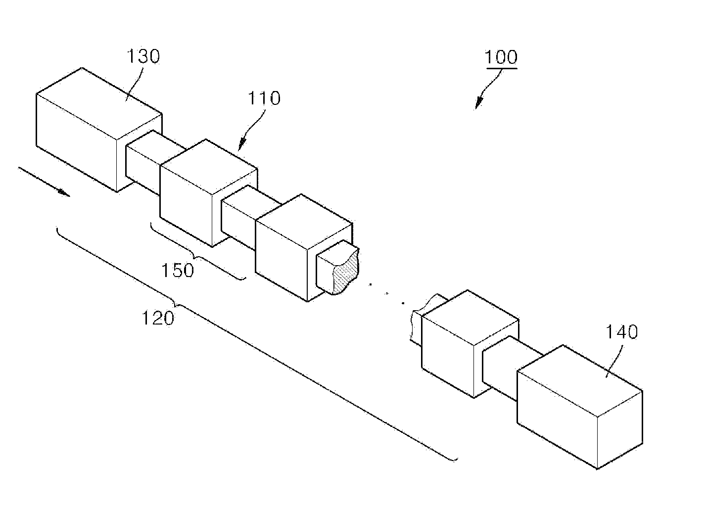
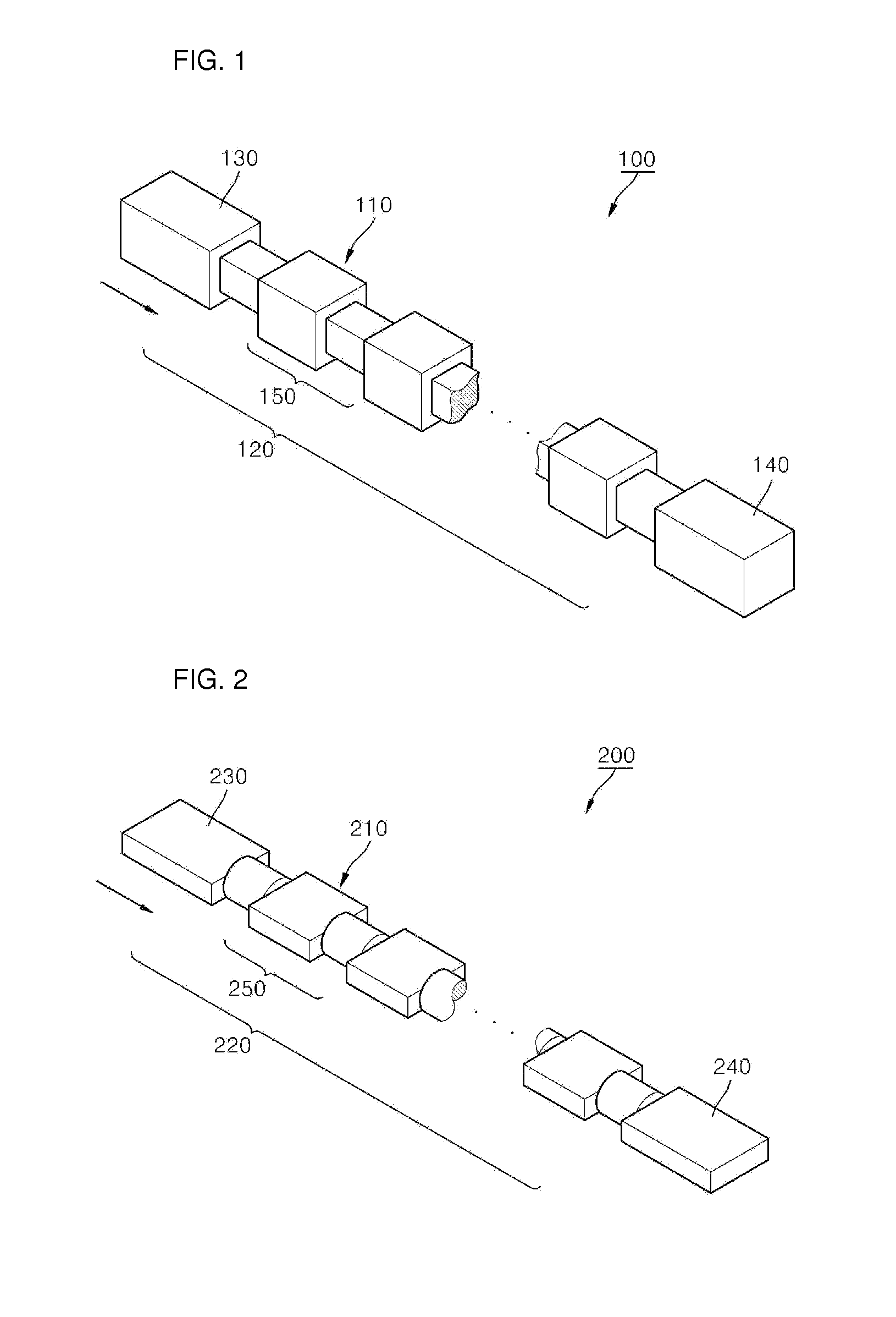
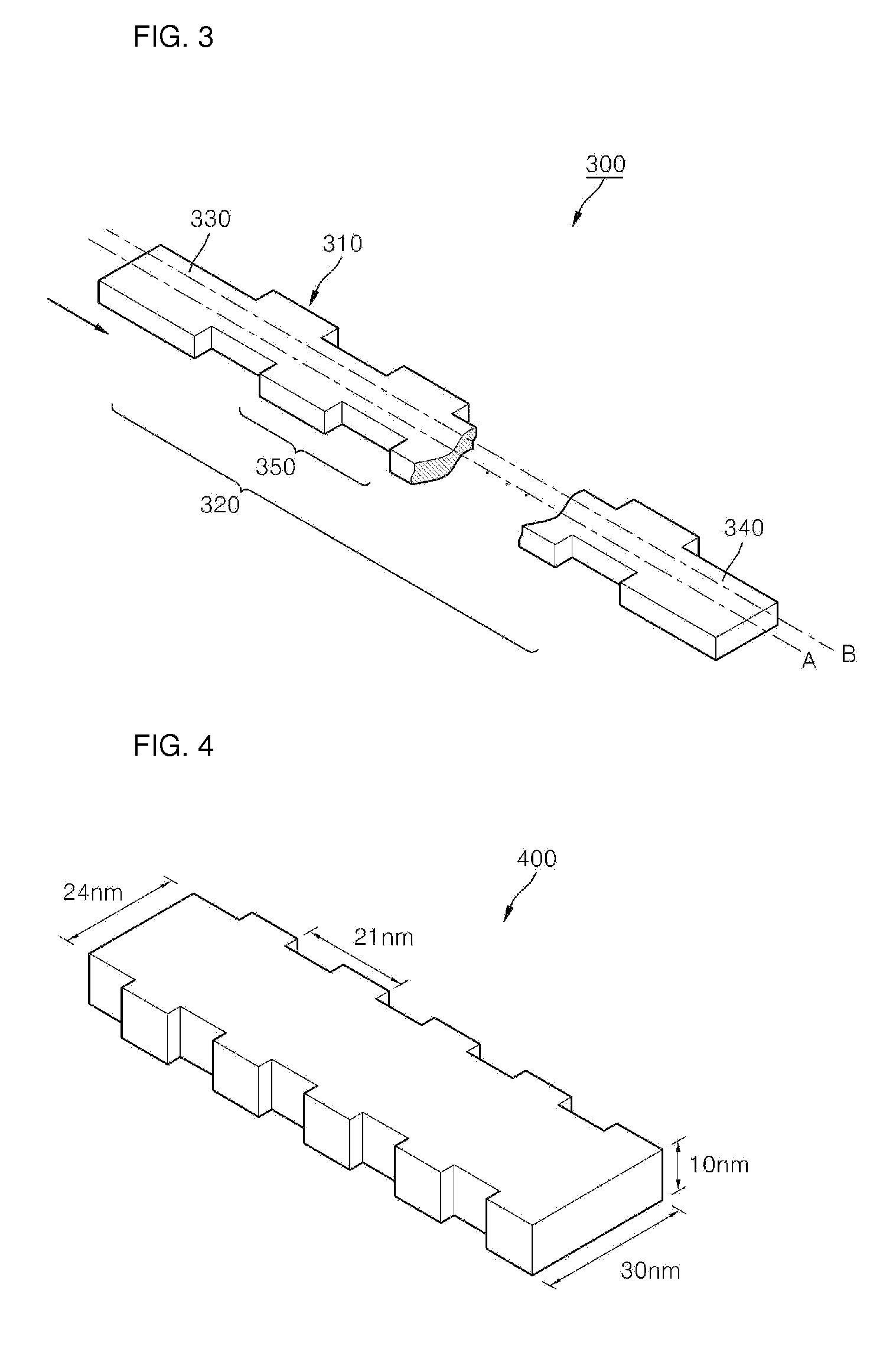
[0024]FIG. 1 to FIG. 3 illustrate preferred exemplary embodiments of a spin wave device according to the invention.

[0025]Referring to FIG. 1 to FIG. 3, a spin wave device 100, 200, 300 according to the invention includes a spin wave waveguide 110, 210, 310 made of magnetic material which guides the spin wave so as to propagate in one direction. The spin wave waveguide 110, 210, 310 includes a magnonic crystal part 120, 220, ...


PUM

PropertyMeasurementUnit
thicknessaaaaaaaaaa
lengthaaaaaaaaaa
thicknessaaaaaaaaaa

Abstract

There is provided a magnonic-crystal spin wave device capable of controlling a frequency of a spin wave. The magnonic-crystal spin wave device according to the invention includes a spin wave waveguide made of magnetic material, and the spin wave waveguide guides the spin wave so as to propagate in one direction, and includes a magnonic crystal part which has a cross-section orthogonal to the direction, and at least one of a shape, area size, and center line of the cross-section periodically changes in the direction. In accordance with the invention, it is possible to easily control the frequency of the spin wave using the spin wave waveguide made of single magnetic material.

Description

CROSS-REFERENCE TO RELATED APPLICATIONS[0001]This application claims priority from Korean Patent Application No. 10-2008-0049681, filed on May 28, 2008 in the Korean Intellectual Property Office, the entire disclosure of which is incorporated herein by reference.TECHNICAL FIELD[0002]The invention relates to a spin wave device, and, more particularly, to a magnonic-crystal spin wave device capable of controlling a frequency of a spin wave.RELATED ARTS[0003]A CMOS-based information processing methodology has an expected limit resulting from following reasons. First, a thickness of a gate oxide film should gradually reduce in order to improve integration level. However, when the thickness of the gate oxide film becomes 0.7 nm, electrons may pass through the gate oxide film in the thickness direction, so that the gate oxide may not act as an insulating film. Second, in case a width of a wire diminishes in order to improve integration level, short-circuit may occur with the wire due to i...

Claims


Application Information

Patent Timeline
Patent Type & Authority Applications(United States)
IPC IPC(8): H03H9/15
CPCH01F1/40Y10T428/32H01P1/218H01F1/408H03H2/00
Inventor KIM, SANG-KOOGLEE, KI-SUKHAN, DONG-SOO
Owner SEOUL NAT UNIV R&DB FOUND
Why Eureka
Try Eureka