

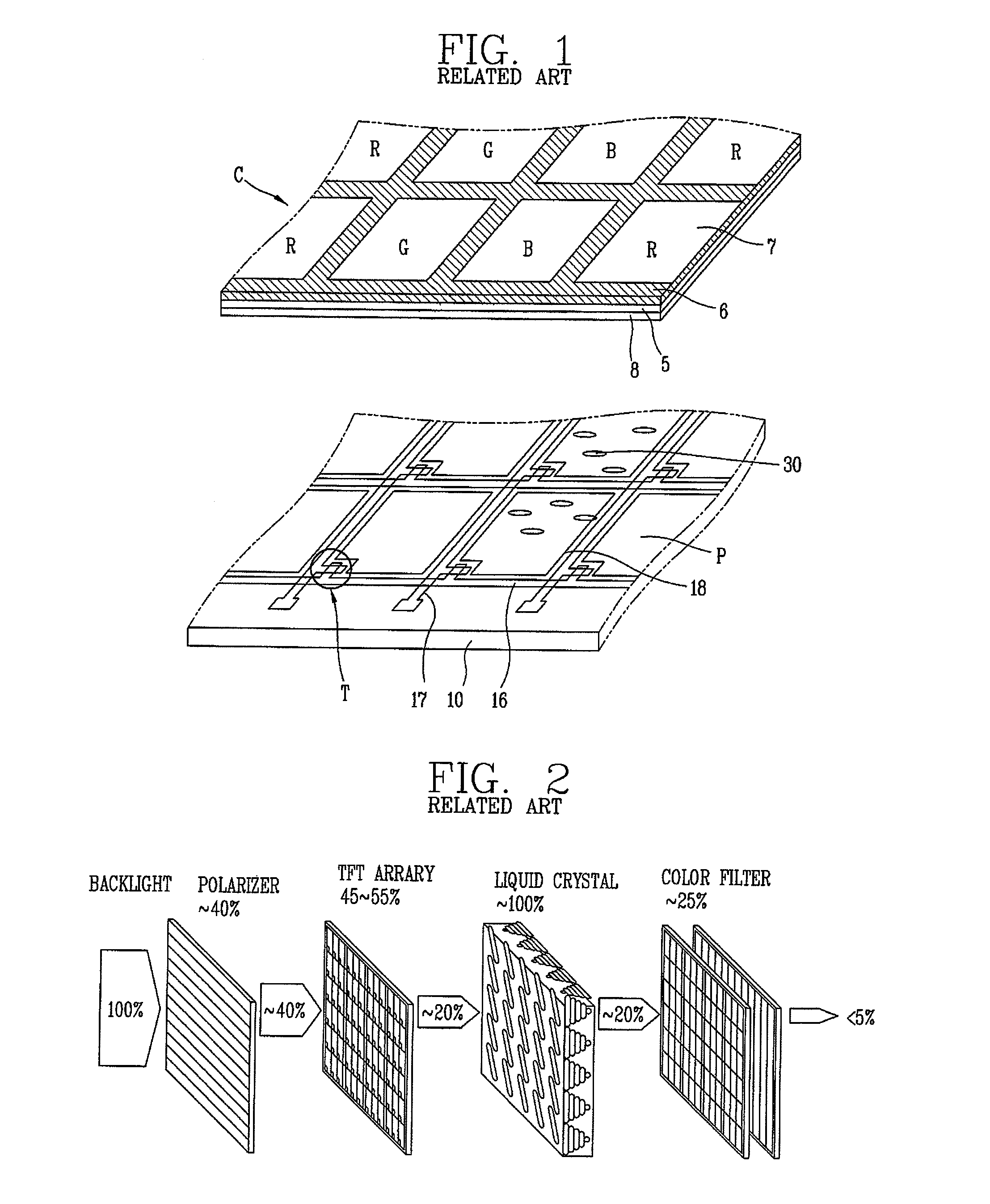
Color filter using surface plasmon and liquid crystal display device
a technology of liquid crystal display and color filter, which is applied in the field of color filter using surface plasmon and liquid crystal display device, can solve the problems of difficult to have a transmittance ratio more than 30%, complicated process of general color filter, and increased power consumption of backlight, so as to enhance the aperture ratio and the transmittance ratio of the lc panel
- Summary
- Abstract
- Description
- Claims
- Application Information
AI Technical Summary
Benefits of technology
Problems solved by technology
Method used
Image

Examples
first embodiment
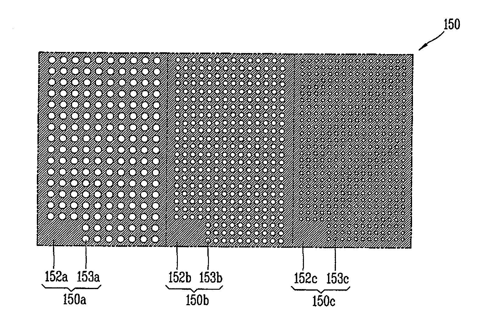
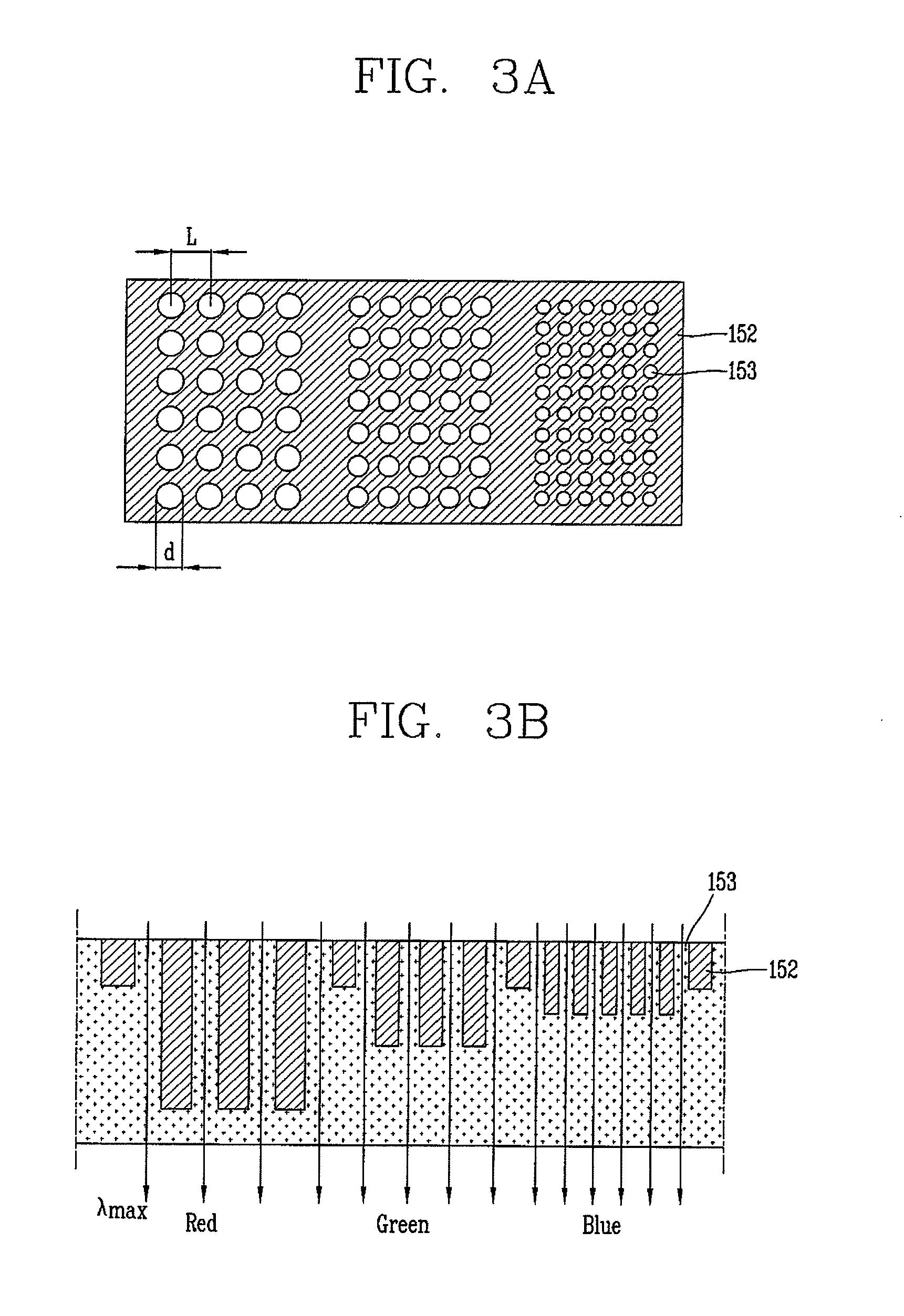
[0061]FIG. 4 is a planar view schematically showing one structure of a color filter according to the present invention, in which RGB sub-color filters each having a quadrangular shape are arranged in the form of stripes.
[0062]FIG. 4 shows a color filter with respect to one pixel composed of sub-color filters corresponding to red, green and blue colors from the left side. However, the present invention is not limited to this.
[0063]As shown, the color filter 150 according to the first embodiment of the present invention comprises a first sub-color filter 150a for implementing a red color by transmitting red light, a second sub-color filter 150b for implementing a green color by transmitting green light, and a third sub-color filter 150c for implementing a blue color by transmitting blue light.
[0064]The first to third sub-color filters 150a, 150b and 150c implement three colors of RGB by transmitting light of RGB wavelengths and reflecting light of other wavelengths. More concretely, f...
second embodiment
[0076]FIG. 6 is a planar view schematically showing one structure of a color filter according to the present invention, in which RGBY (or RGBC) sub-color filters each having a quadrangular shape are arranged in the form of stripes.
[0077]FIG. 6 shows a color filter with respect to one pixel composed of sub-color filters corresponding to red, green, blue, and yellow colors from the left side. However, the present invention is not limited to this.
[0078]As shown, the color filter 250 according to the second embodiment of the present invention comprises a first sub-color filter 250a for implementing a red color by transmitting red light, a second sub-color filter 250b for implementing a green color by transmitting green light, a third sub-color filter 250c for implementing a blue color by transmitting blue light, and a fourth sub-color filter 250d for implementing a yellow color by transmitting yellow light.
[0079]As aforementioned, the fourth sub-color filter 250d may implement a cyan co...
third embodiment
[0092]FIG. 8 is a planar view schematically showing one structure of a color filter according to the present invention, in which quadrangular-RGBYC sub-color filters are arranged in the form of stripes.
[0093]FIG. 8 shows a color filter with respect to one pixel composed of sub-color filters corresponding to red, green, blue, yellow and cyan colors from the left side. However, the present invention is not limited to this.
[0094]As shown, the color filter 350 according to the third embodiment of the present invention comprises a first sub-color filter 350a for implementing a red color by transmitting red light, a second sub-color filter 350b for implementing a green color by transmitting green light, a third sub-color filter 350c for implementing a blue color by transmitting blue light, a fourth sub-color filter 350d for implementing a yellow color by transmitting yellow light, and a fifth sub-color filter 350e for implementing a cyan color by transmitting cyan light.
[0095]The first to...
PUM
| Property | Measurement | Unit |
|---|---|---|
| transmittance | aaaaa | aaaaa |
| transmittance ratio | aaaaa | aaaaa |
| transmittance | aaaaa | aaaaa |
Abstract
Description
Claims
Application Information