
Chip-removing tool

a technology of chip removal and tool, which is applied in the direction of tool workpiece connection, shaping cutter, manufacturing tools, etc., can solve the problems of high functional reliability and achieve the effects of small construction space, small construction space, and small for

Inactive Publication Date: 2011-05-05
MAPAL FAB FUR PRAZIONSWERKZEUGE DR KRESS KG
View PDF0 Cites 0 Cited by
  • Summary
  • Abstract
  • Description
  • Claims
  • Application Information

AI Technical Summary

Benefits of technology

[0004]The object of the invention, therefore, is to provide a chip-removing tool which avoids the above disadvantage and in which the adjusting device requires a very small construction space.
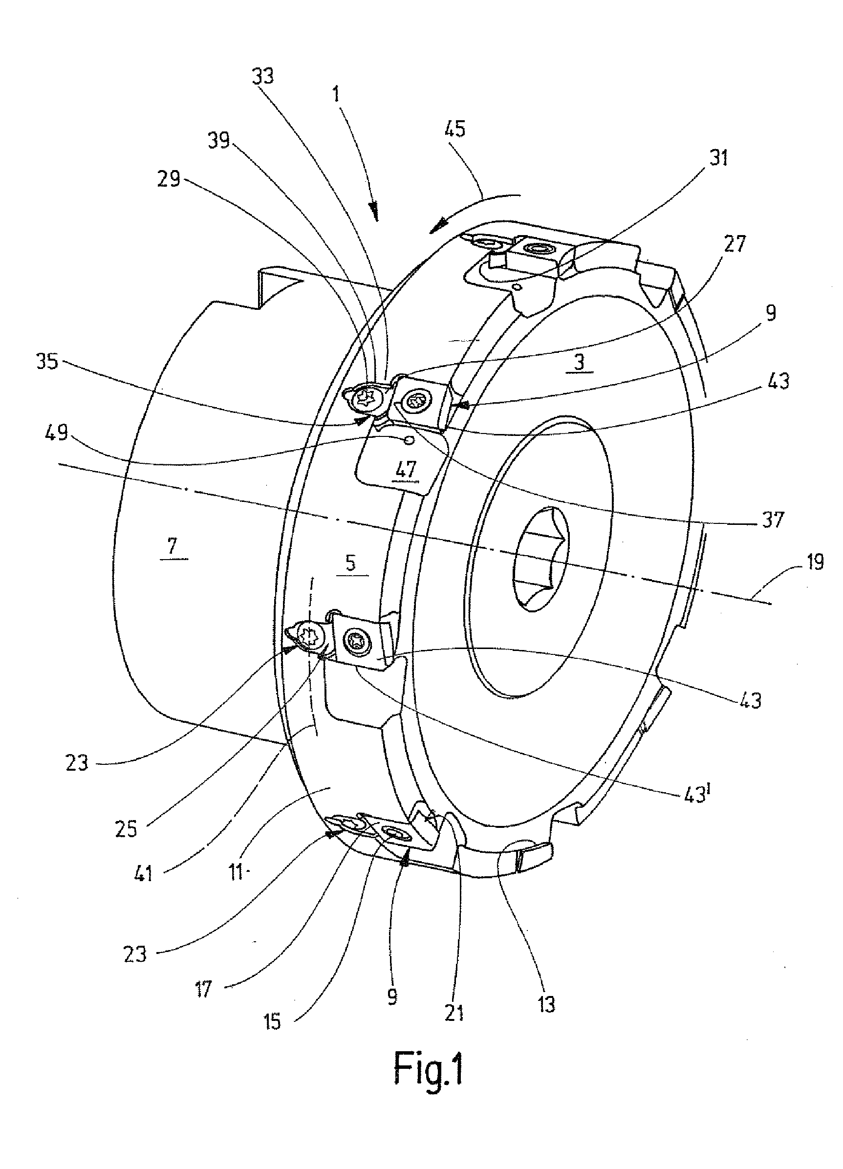
[0005]To achieve this object, a chip-removing tool is proposed which comprises the features mentioned below. It therefore has a basic body, a cutting body having at least one geometrically defined cutting edge, and an adjusting device with an adjusting element which can be expanded by means of an adjusting screw. This it possible for the at least one cutting edge to be set. The chip-removing tool is distinguished in that the adjusting element of the adjusting device is designed as a ring which is supported, on the one hand, on the cutting body and, on the other hand, on the basic body of the chip-removing tool. The ring can be designed to be thin, without functional disadvantages occurring, so that, when the at least one geometrically defined cutting edge is being set, little effort is needed for expanding the adjusting element of the adjusting device, and only a very small construction space is required.
[0007]An especially preferred exemplary embodiment of the chip-removing tool is distinguished in that the cutting body is designed as a knife plate, and in that the thickness of the ring is at most as large as the thickness of the knife plate. On account of the small construction space of an adjusting device of this type, the chip-removing tool is weakened to only a very little extent, thus resulting in high functional reliability.

Problems solved by technology

On account of the small construction space of an adjusting device of this type, the chip-removing tool is weakened to only a very little extent, thus resulting in high functional reliability.

Method used


Image

  • Chip-removing tool
  • Chip-removing tool
  • Chip-removing tool

Examples


Embodiment Construction

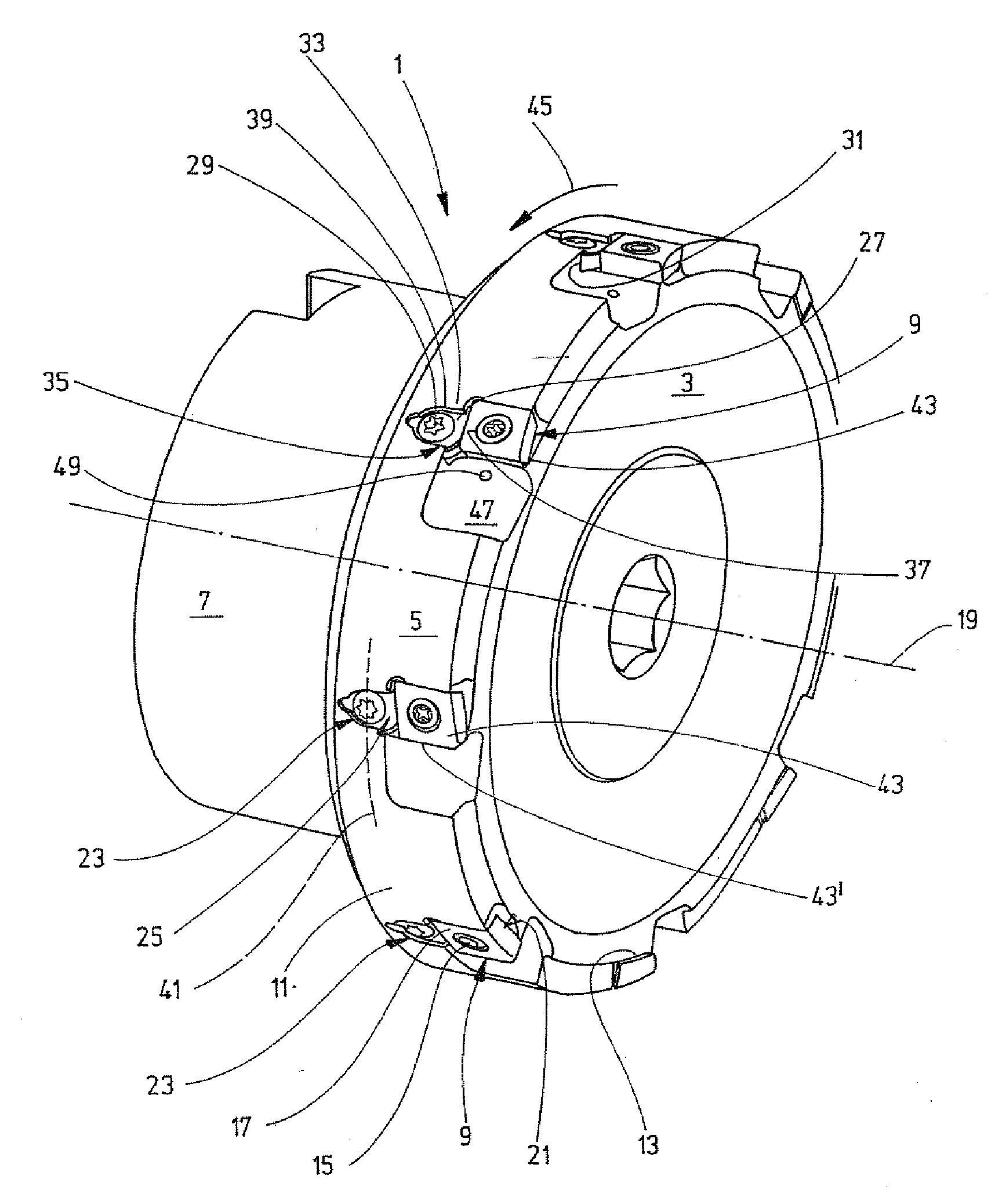
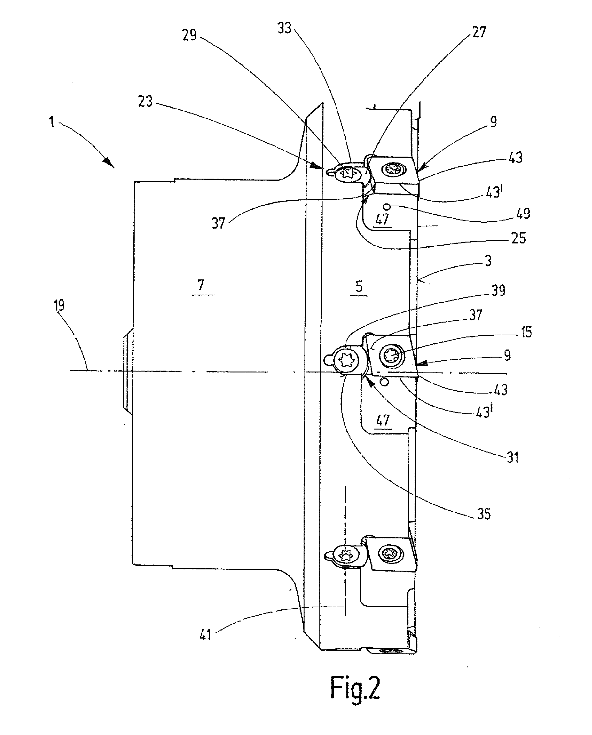
[0013]The chip-removing tool 1 illustrated in FIG. 1 is designed, for example, as a surface milling cutter. It is reproduced in a perspective illustration, so that its front side and also its circumferential face can be seen. The chip-removing tool, designated below briefly as the tool 1, has here a shank 7 which serves for connecting the tool to a machine tool, directly or via an intermediate piece, an adaptor or the like.

[0014]The tool 1 has at least one cutting body designed here as a knife plate 9. The exemplary embodiment reproduced here is provided with eight identical knife plates 9 which are fastened to the basic body 11 of the tool 1. Here, each knife plate is accommodated in a suitable recess 13 and is fastened tangentially to the tool 1 by means of a tension screw 15. The screw penetrates perpendicularly through the knife plate 9, that is, the axis of rotation, not reproduced here, of the tension screw 15 stands perpendicularly to the mid-axis 19 of the tool 1 which also ...


PUM

PropertyMeasurementUnit
thicknessaaaaaaaaaa
axis of rotationaaaaaaaaaa
forceaaaaaaaaaa

Abstract

A chip-removing tool, includes a basic body, at least one cutting body attachable to the basic body and having at least one geometrically defined cutting edge. An adjusting device has an adjusting element expandable by an adjusting screw. The adjusting element is a slotted ring which is supported, on the one hand, on the cutting body and, on the other hand, on the basic body of the chip-removing tool.

Description

CROSS REFERENCE TO RELATED APPLICATION[0001]The present application is a 35 U.S.C. §§371 national phase conversion of PCT / EP2008 / 006900, filed Aug. 22, 2008, which claims priority of German Application No. 10 2007 040 936.4, filed Aug. 30, 2007, the disclosure of which is incorporated by reference herein. The PCT International Application was published in the German language.BACKGROUND OF THE INVENTION[0002]The invention relates to a chip-removing tool.[0003]Chip-removing tools of the type referred to here are known. They have a basic body with at least one cutting body which is fastened thereto and which comprises at least one geometrically defined cutting edge. An adjusting device makes it possible to set the exact position of the cutting edge. It became apparent that known adjusting devices require a relatively large construction space which weakens the basic body of the tool.SUMMARY OF THE INVENTION[0004]The object of the invention, therefore, is to provide a chip-removing tool ...

Claims


Application Information

Patent Timeline
Patent Type & Authority Applications(United States)
IPC IPC(8): B23P15/28
CPCB23C5/2417B23C5/2462B23C5/2493B23C2240/24Y10T407/2242B23C2265/08Y10T407/24Y10T407/1922B23C2260/68B23C5/24B23C5/2234
Inventor STROM, RUDOLF
Owner MAPAL FAB FUR PRAZIONSWERKZEUGE DR KRESS KG
Learn More