Chain guide mechanism

Active Publication Date: 2011-05-05
TSUBAKIMOTO CHAIN CO
View PDF9 Cites 3 Cited by
  • Summary
  • Abstract
  • Description
  • Claims
  • Application Information

AI Technical Summary

Benefits of technology

[0010]The structure described above, allows the guide bridge to use short arms which can be light in weight, but are not as easily deformed as longer arms. With the use of short arms, it is possible to prevent the guide mounting holes from being accidentally disengaged from the mounting bosses during operation of the chain drive as well as during assembly and maintenance.
[0011]The structure also makes it possible to hold the chain together with the chain guides, and thereby facilitate assembly and maintenance by assembling the chain, guide bridge and guides in advance of installation on an engine block.
[0012]One of the chain guides can be provided with a projection on the outer circumference of at least one of its cylindrical mounting bosses, and the guide mounting hole receiving the mounting boss having the projection is formed with a notch that mates with the projection, whereby rotation of the chain guide relative to the guide bridge is prevented. The projection and notch provide a convenient way to mount a fixed chain guide and prevent its rotation, and further facilitate assembly and maintenance.
[0013]Each of the opposed parts of each arm of the guide bridge can have a guide deviation preventing projection that projects toward the opposite part of the arm. The deviation preventing projections limit lateral movement of

Problems solved by technology

The structure described above, allows the guide bridge to use short arms w

Method used


Image

  • Chain guide mechanism
  • Chain guide mechanism
  • Chain guide mechanism

Examples


Embodiment Construction

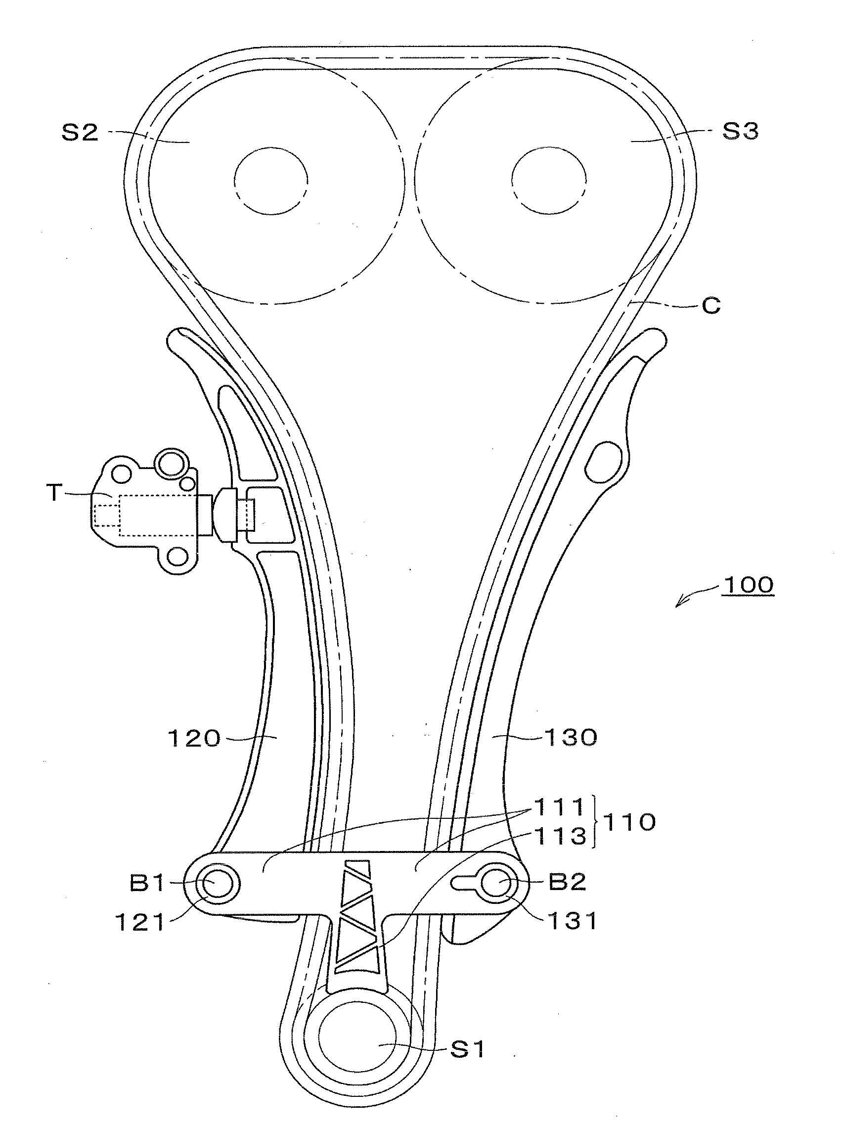
[0028]FIG. 1 shows a chain guide mechanism 100 in an engine timing drive in which an endless timing chain C is engaged with a driving sprocket S1 on an engine crankshaft, and with a pair of driven sprockets, S2 and S3, on valve-operating camshafts. The timing drive is typically housed within a space between the engine block and a timing chain cover.

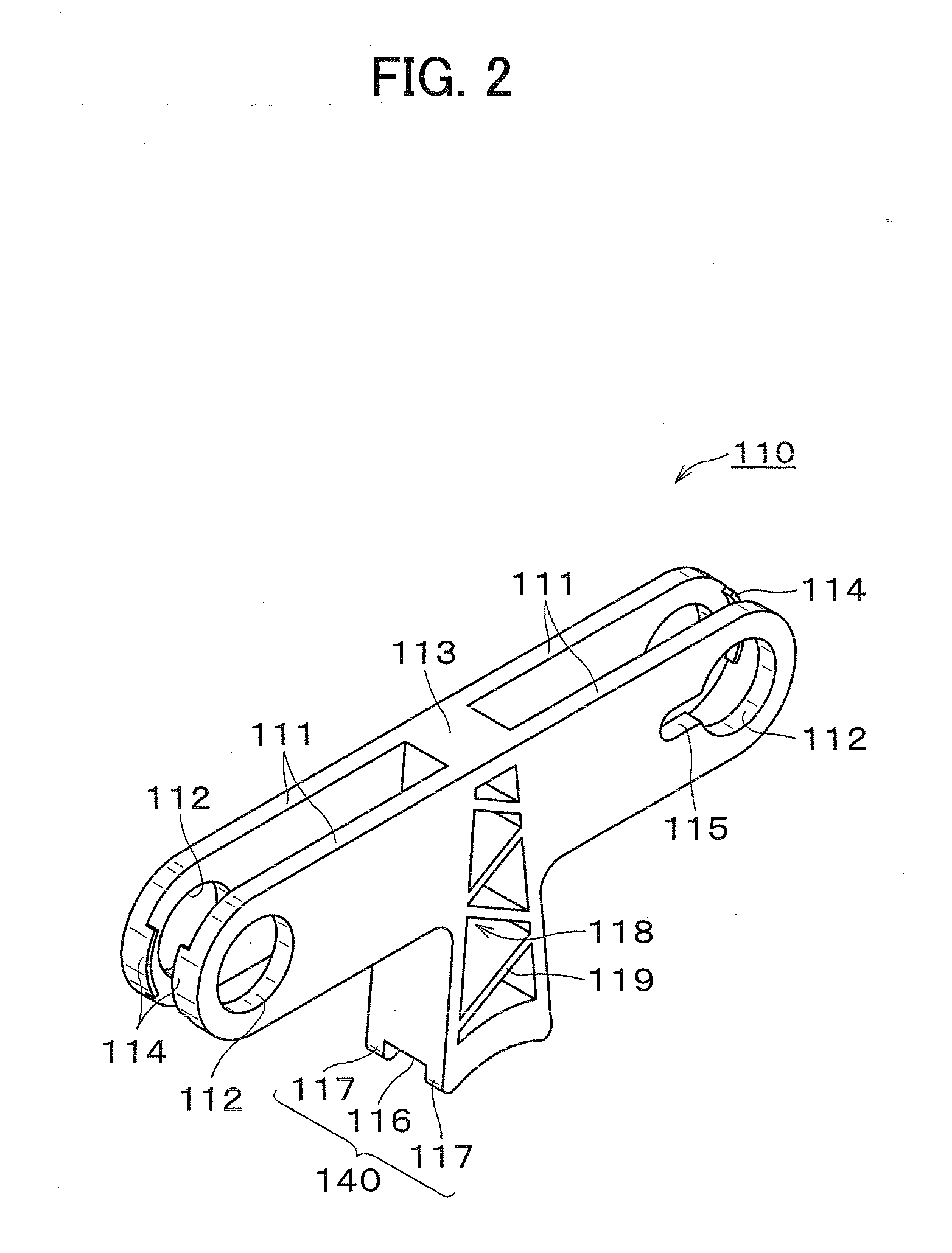
[0029]The chain guide mechanism 100 includes a guide bridge 110 having a pair of arms 111 which extend in opposite directions from a central location, and to which are attached respectively a pivoted chain guide 120, which oscillates with changing tension in the chain C, and a fixed chain guide 130. The bridge also includes a base portion 113 which extends perpendicularly from the oppositely extending arms 111, from the central location between the arms so that the guide bridge is T-shaped. An edge of the base portion 113 of bridge 110 is in close relationship to the driving sprocket S1.

[0030]The chain guide mechanism 100 is fixed within ...


PUM


Abstract

In a chain guide mechanism, fixed and movable guides are attached to a guide bridge by cooperation of bosses on the guides with boss-receiving holes formed in spaced-apart elements of arms of the bridge. A fixed guide is held against rotation by cooperation of a projection on its mounting boss with a notch in a boss-receiving hole in a guide bridge arm element. A base, extending from an intermediate location at which the arms come together has a pressing structure that engages bosses on a driving sprocket, and a groove for receiving teeth of the driving sprocket.

Description

CROSS REFERENCE TO RELATED APPLICATION [0001]This application claims priority under Title 35, United States Code, §119 on the basis of Japanese Patent Application No. 2009-253032, filed on Nov. 4, 2009. The disclosure of Japanese Patent Application No. 2009-253032 is herein incorporated by reference in its entirety.FIELD OF THE INVENTION [0002]The invention relates to a chain guide mechanism comprising a plurality of chain guides for sliding engagement with a chain, and a guide bridge for holding the chain guides. The invention relates more specifically to a chain guide mechanism for use in an engine timing drive to guide and maintain tension in an endless timing chain such as a silent chain, a roller chain, or the like engaged in driven relationship with a crankshaft sprocket and in driving relationship with one or more camshaft sprockets within a timing drive compartment, which is typically formed between an engine block and a timing chain cover.BACKGROUND OF THE INVENTION [0003]F...

Claims


Application Information

Patent Timeline
IPC IPC(8): F16H7/18F16H7/08
CPCF16H7/08F16H2007/0893F16H2007/0874
Inventor KONNO, MASAHIKOMORI, KAORIKUREMATSU, YUJIKOBARA, AKIRAHIRAYAMA, MANABU
Owner TSUBAKIMOTO CHAIN CO
Why Eureka
Try Eureka