Engine control system with algorithm for actuator control

a control system and actuator technology, applied in the direction of electric control, machines/engines, instruments, etc., can solve the problems of imposing a heavy burden on control system manufacturers, affecting the efficiency of the control system, and the deviation of the output-related value of the engine from the required value, so as to minimize the mutual interference between such combustion parameters and minimize the mutual interference

Active Publication Date: 2011-05-05
DENSO CORP
View PDF16 Cites 20 Cited by
  • Summary
  • Abstract
  • Description
  • Claims
  • Application Information

AI Technical Summary

Benefits of technology

[0045]The engine output-related values may also include at least two of the amount of NOx, the amount of PM, the amount of CO, and the amount of HC. The engine output-related values associated with such exhaust emissions are more likely to have the tradeoff relationship. The engine control apparatus is, therefore, effective in treating such engine output-related values.
[0046]The combustion parameters may include the ignition timing and the ignition delay. Such kinds of combustion parameters are typical physical quantities representing the combustion conditions in a cylinder of the engine and related closely with each other. The use of the combustion parameter arithmetic expression and the controlled variable arithmetic expression, therefore, minimizes the mutual interference between such combustion parameters.
[0047]The controlled variables may include at least two of the injection quantity of fuel, the injection timing of fuel, the number of injections of fuel, the supply pressure of fuel, the EGR amount, the supercharging pressure, and the open / close timing of intake or exhaust valve. Such controlled variables are typical variables used in the engine control system and more likely to interfere mutually with each other. The use of the controlled variable arithmetic expression, therefore, minimizes the mutual interference between such controlled variables.

Problems solved by technology

The above engine control systems have the drawback in that correlations between the engine output-related values and the controlled values usually change with a change in environmental is condition such as the temperature of outside air or due to an individual variability of the engine, which will result in deviations between the engine output-related values from the required values.
This, however, requires the measurement of emissions from the engine such as NOx or PM, the output torque from the engine, the fuel consumption in the engine, or noises arising from combustion of fuel in the engine (i.e., the engine output-related values), thus resulting in a great increase in cost to install the system in automotive vehicles.
The making of the correction map requires lots of data on correspondence between the engine output-related values and the controlled variables under environmental conditions that the correlations are needed to be corrected, thus imposing a heavy burden on control system manufacturers or resulting in possibility of a difficulty in bringing all the engine output-related values into agreement with required values thereof.
Moreover, some of the engine output-related values can be measured using vehicle-installed sensors directly (e.g., the measurement of NOx using a NOx sensor) or indirectly (e.g., the measurement of PM using an A / F sensor) in order to learning the correlations between the engine output-related values and the controlled variables partially, however, the problem is encountered in that when the responsiveness of the sensors is low undesirably, the partial learning needs to be made only in a limited condition, for example, where the engine is running in the steady state.

Method used


Image

  • Engine control system with algorithm for actuator control
  • Engine control system with algorithm for actuator control
  • Engine control system with algorithm for actuator control

Examples


Embodiment Construction

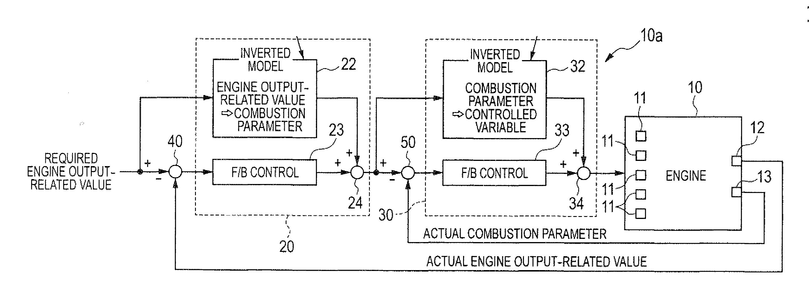
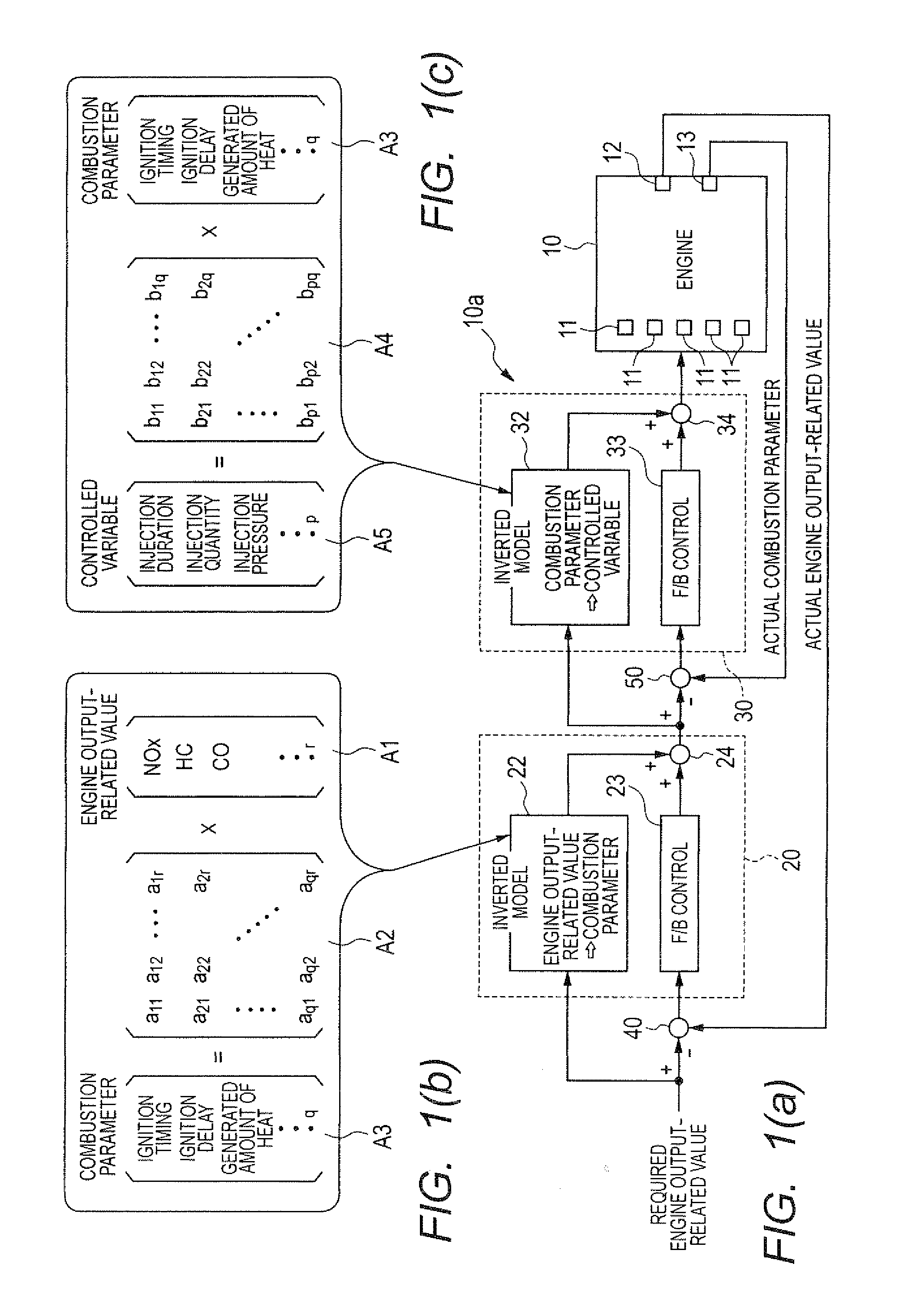
[0064]Referring to the drawings, wherein like reference numbers refer to like parts in several views, particularly to FIG. 1(a), there is shown an engine control system according to the first embodiment which is designed to control an operation of an internal combustion engine 10 for automotive vehicles. The following discussion will refer to, as an example, a self-ignition diesel engine in which fuel is sprayed into four cylinders #1 to #4 at a high pressure.

[0065]FIG. 1(a) is a block diagram of the engine control system implemented by an electronic control unit (ECU) 10a which works to control operations of a plurality of actuators 11 to regulate fuel combustion conditions of the engine 10 for bringing output characteristics of the engine 10 into agreement with desired ones.

[0066]The actuators 11 installed in a fuel system are, for example, fuel injectors which spray fuel into the engine 10 and a high-pressure pump which controls the pressure of fuel to be fed to the fuel injector...


PUM


Abstract

An engine control apparatus which may be employed in automotive vehicles. The engine control apparatus is equipped with a controlled variable arithmetic expression which defines correlations between combustion parameters associated with combustion conditions of an engine and controlled variables actuators for an operation of the engine. This eliminates the need for finding relations of optimum values of the controlled variables to the combustion parameters through adaptability tests, which results in a decrease in burden of an adaptability test work and a map-making work on manufacturers. The engine control apparatus also works to learn or optimize the controlled variable arithmetic expression based on actual values of the combustion parameters, thereby avoiding undesirable changes in correlations, as defined by the controlled variable arithmetic expression, due to a change in environmental condition.

Description

CROSS REFERENCE TO RELATED DOCUMENT[0001]The present application claims the benefit of priority of Japanese Patent Application No. 2009-251866 filed on Nov. 2, 2009, the disclosures of which are incorporated herein by reference.BACKGROUND OF THE INVENTION[0002]1. Technical Field of the Invention[0003]The present invention relates generally to an engine control system which may be employed in automotive vehicles and is designed to use an algorithm to control operations of actuators such as a fuel injector and an EGR (Exhaust Gas Recirculation) valve to regulate a combustion condition of fuel in an internal combustion engine and also to control output characteristics of the engine.[0004]2. Background Art[0005]Engine control systems are known which determine controlled variables such as the quantity of fuel to be injected into an engine (which will also be referred to as an injection quantity), the injection timing, the amount of a portion of exhaust gas to be returned back to the inle...

Claims


Application Information

Patent Timeline
Patent Type & Authority Applications(United States)
IPC IPC(8): G06F19/00
CPCF02D35/02F02D2250/18F02D35/023F02D35/028F02D37/02F02D41/0002F02D41/0052F02D41/1401F02D41/1438F02D41/2448F02D41/2454F02D41/3836F02D41/40F02D2041/1419F02D2041/1434F02D2200/025F02D2200/0625F02D35/021
Inventor ASANO, MASAHIROTAKASHIMA, YOSHIMITSUISHIZUKA, KOJISASAKI, SATORUHIGUCHI, KAZUHIROIKEDA, SUMITAKAMORIMOTO, YOUHEINISHIMURA, MITSUHIRO
Owner DENSO CORP
Why Eureka
Try Eureka