Serial networking fiber-to-the-seat inflight entertainment system

a technology of inflight entertainment and fiber-to-the-seat, which is applied in the field of inflight entertainment systems with fiber-to-the-seat fiber-to-the-seat fiber-to-the-seat, which can solve the problems of single failure of the switch unit, high implementation cost and complexity of the system, and high cost of the system architectur

Active Publication Date: 2011-05-05
ANUVU IP HLDG LLC
View PDF69 Cites 34 Cited by
  • Summary
  • Abstract
  • Description
  • Claims
  • Application Information

AI Technical Summary

Benefits of technology

[0011]In some embodiments, the loop-free serially-connected networking data paths are maintained by removing a selected link from a previous serially-connected serially-connected networking data path. In some embodiments, the selected link is selected using hop count information. In some embodiments, the selected link is selected to minimize the maximum number of hops between any of the active serially-connected networking line replaceable units and either of the two head end line replaceable units.

Problems solved by technology

However, this FTTS system has certain drawbacks.
First, each server switch unit (SSU) is a single point of failure for all VDUs and any cabin management terminal (CMT) that connects directly to that SSU.
Second, the implementation of a star wired network topology wherein each VDU has a dedicated optical fiber “home run” to a head end SSU adds cost and complexity to the system.
The high cost of aircraft grade fiber and fiber optic connectors, coupled with the cost and complexity of installing these fiber components, make this architecture very expensive to implement.

Method used


Image

  • Serial networking fiber-to-the-seat inflight entertainment system
  • Serial networking fiber-to-the-seat inflight entertainment system
  • Serial networking fiber-to-the-seat inflight entertainment system

Examples


Embodiment Construction

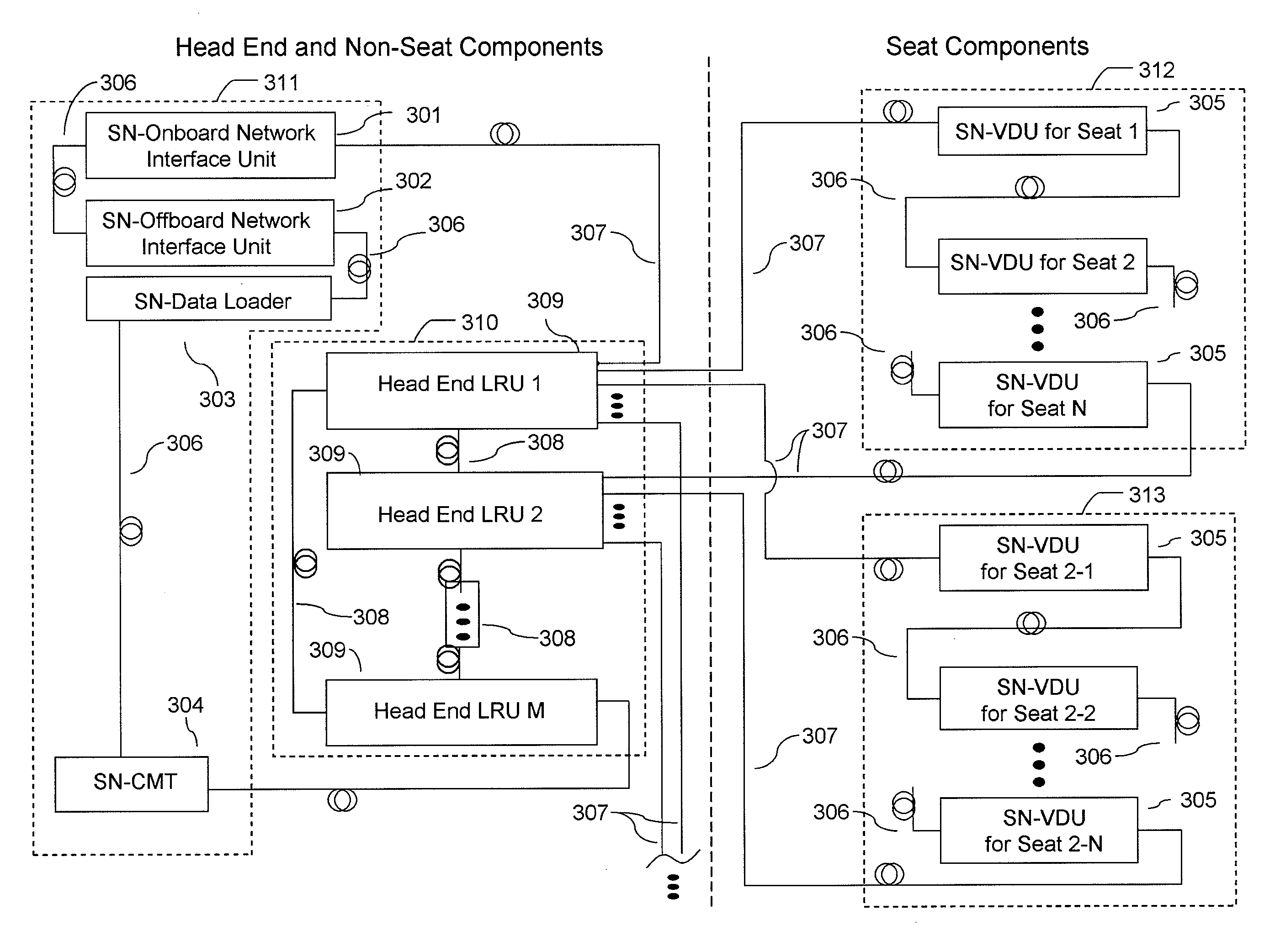
[0039]FIG. 3 shows an inflight entertainment (IFE) system with serial networking line replaceable unit (SN-LRU) chains 311-313 and a head end line replaceable unit (HE-LRU) ring 310 in some embodiments of the invention. As illustrated, SN-LRU chain 311 and HE-LRU ring 310 are positioned outside of the seats, while SN-LRU chains 312, 313 are positioned at the seats. In these embodiments, multiple HE-LRUs 309 are physically connected by ring via fiber optic links 308. Multiple chains of SN-LRUs 301-305 are physically connected to HE-LRUs 309 at their edges (ends) via links 307, for example fiber optics, such that the two edges of each chain are physically connected to a different one of HE-LRUs 309. Many types of SN-LRUs can be employed, for example serial networking onboard network interface unit 301, serial networking offboard network interface unit 302, serial networking data loader 303, serial networking CMT 304 (generally positioned in the galley), and serial networking VDUs 305....


PUM


Abstract

An entertainment system that exhibits advantages of fiber-to-the-seat systems, has improved failure recovery characteristics, and reduces the connection components is disclosed. In one aspect, an inflight entertainment system comprises a plurality of head end line replaceable units physically interconnected in a ring configuration and a plurality of serially-connected networking line replaceable units physically interconnected in a serial configuration, wherein two of the serially-connected networking line replaceable units at the edge of the serial configuration are physically interconnected with two of the head end line replaceable units, respectively, wherein a loop-free head end data path is maintained between active head end line replaceable units by regulating link participation in the head end data path, and wherein one or more loop-free serially-connected networking data paths are maintained between at least one of the two head end line replaceable units and active serially-connected networking line replaceable units by regulating link participation in the serially-connected networking data paths.

Description

CROSS-REFERENCE TO RELATED APPLICATIONS[0001]This application claims the benefit of U.S. provisional application No. 61 / 273,584 entitled “SERIAL NETWORKING FIBER-TO-THE-SEAT INFLIGHT ENTERTAINMENT SYSTEM,” filed on Aug. 6, 2009 and U.S. provisional application No. 61 / 274,726 entitled “SERIAL NETWORKING FIBER-TO-THE-SEAT INFLIGHT ENTERTAINMENT SYSTEM NETWORK MANAGEMENT,” filed on Aug. 20, 2009, the contents of both of which are incorporated herein by reference in their entirety.BACKGROUND OF THE INVENTION[0002]Inflight entertainment systems have evolved significantly over the last 25 years. Prior to 1978, IFE systems consisted of audio-only systems. In 1978, Bell and Howell (Avicom Division) introduced a group viewing video system based on video cassette tapes. In 1988, Airvision introduced the first in-seat video system allowing passengers to choose between several channels of broadcast video. In 1997, Swissair installed the first interactive video on demand (VOD) system. Currently,...

Claims


Application Information

Patent Timeline
Patent Type & Authority Applications(United States)
IPC IPC(8): H04N7/18H04L45/18
CPCH04L12/40182H04L12/437H04L2012/4028H04N21/2146H04L41/0668H04L41/0677H04L67/12H04B10/038H04L45/18H04N21/2221H04N21/2225H04N21/41422H04N21/43632
Inventor PETRISOR, GREGORY C.CLINE, DOUGLASWICKLUND, ROLF
Owner ANUVU IP HLDG LLC
Why Eureka
Try Eureka