Machine tool and tool holder

a tool holder and machine tool technology, applied in the field of machine tools and tool holders, can solve problems such as interference with the coupling section, and achieve the effect of short time-consuming and easy-to-use effects

Inactive Publication Date: 2011-05-12
DMG MORI SEIKI CO LTD
View PDF18 Cites 22 Cited by
  • Summary
  • Abstract
  • Description
  • Claims
  • Application Information

AI Technical Summary

Benefits of technology

[0009]An object of the present invention is to provide a machine tool that can achieve a clamping force sufficient to withstand the load im

Problems solved by technology

In the case where an automatic tool changer of the double arm scheme is applied to a machine tool including a positioning device of such a tool bit holder, the double arm that moves over the end face

Method used


Image

  • Machine tool and tool holder
  • Machine tool and tool holder
  • Machine tool and tool holder

Examples


Embodiment Construction

[0029]Embodiments of the present invention will be described with reference to the drawings. In the drawings referred to hereinafter, the same or corresponding members have the same reference number allotted.

[0030]Configuration of Machine Tool

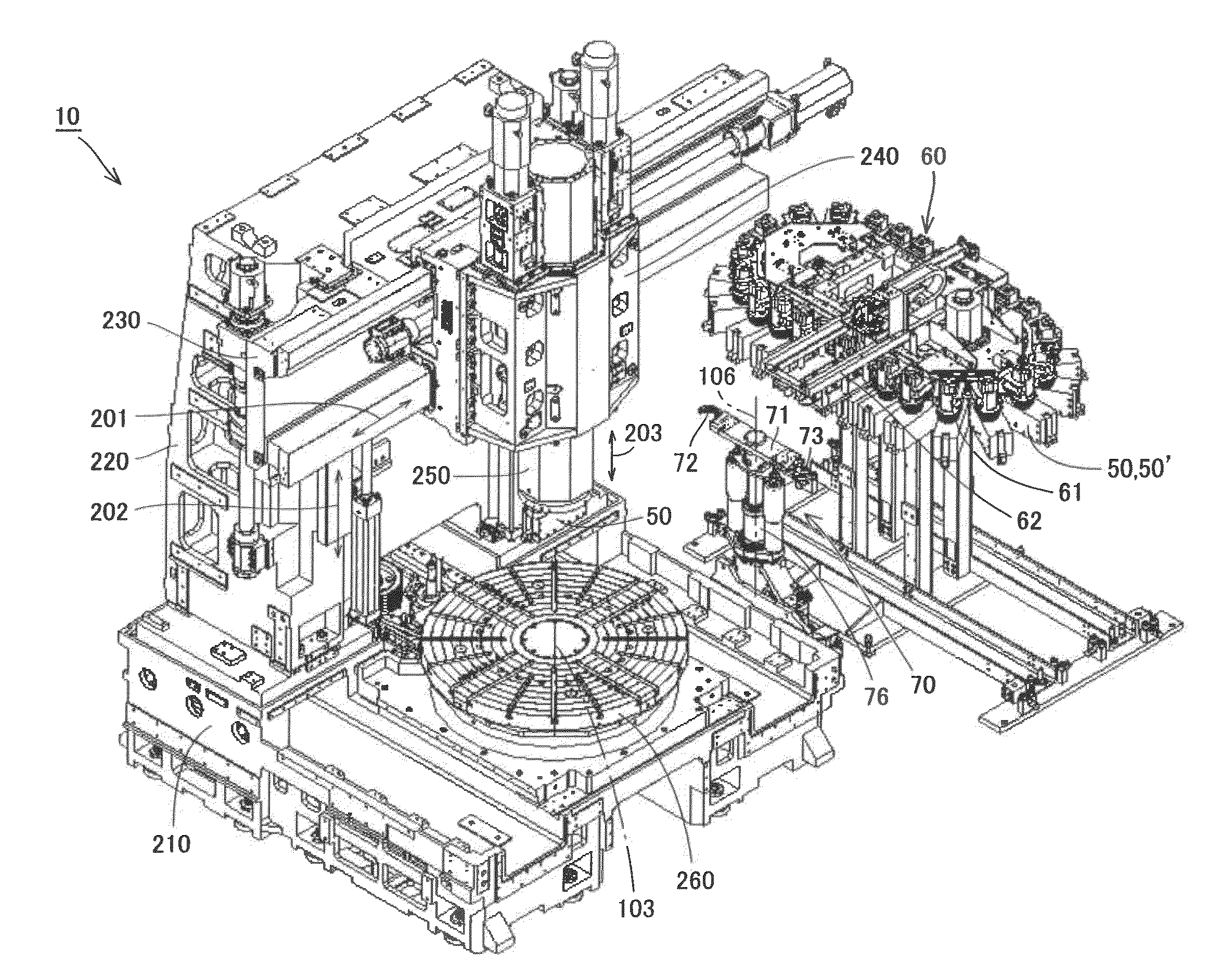
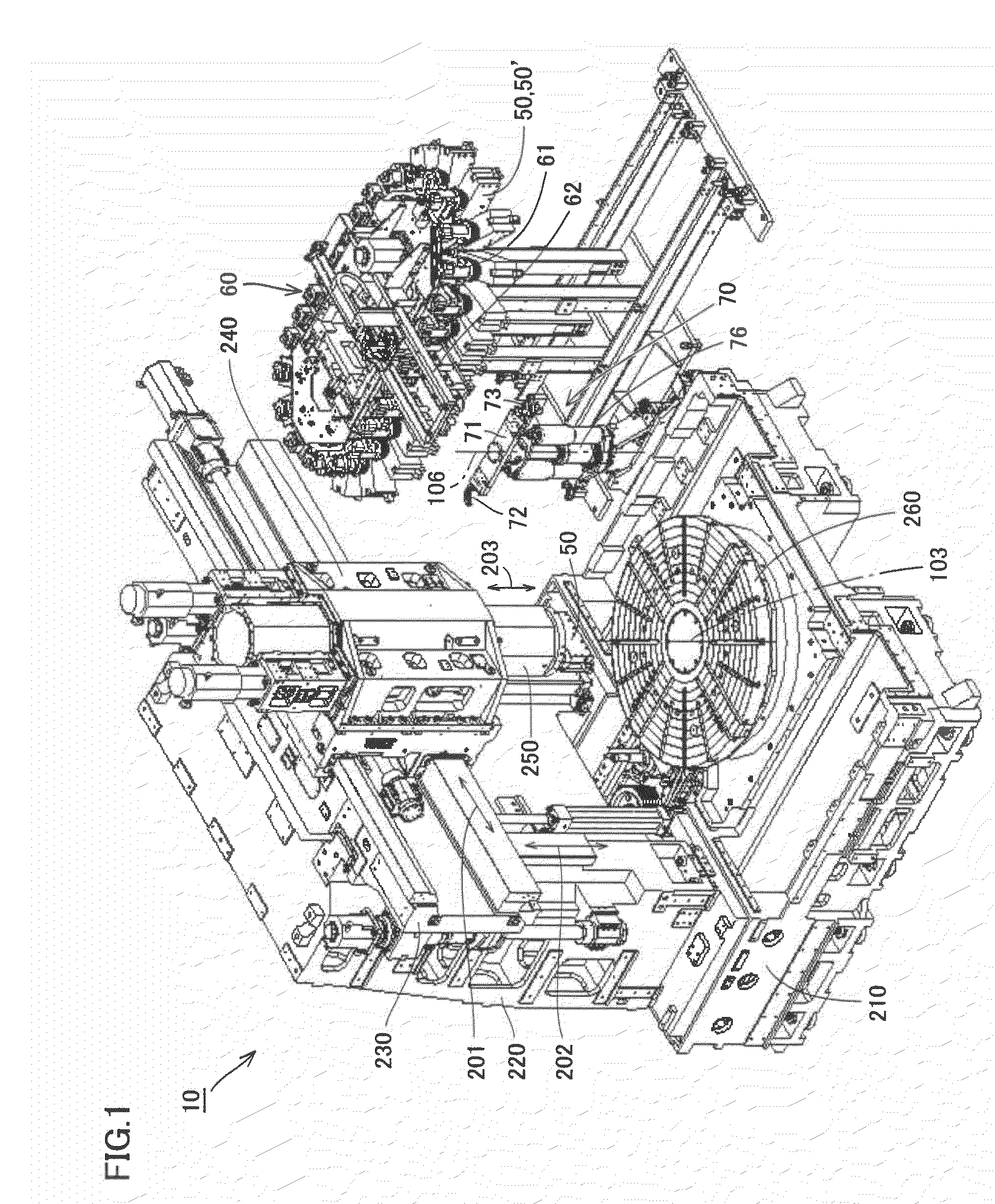
[0031]Referring to the perspective view of FIG. 1, a machine tool 10 according to an embodiment of the present invention has a turning function using a fixed tool, and a milling function using a rotary tool. Machine tool 10 is a lathe having a milling function. Machine tool 10 is a vertical lathe for cutting a workpiece (work) held at a table by a rotary movement of a table centered about a vertical axis, and a feeding movement of a tool bit that is a fixed tool.

[0032]The entire configuration of machine tool 10 according to the present embodiment will be first described. Machine tool 10 includes, as the main component, a bed 210, a column 220, a cross rail 230, a saddle 240, a ram 250, and a table 260.

[0033]Bed 210 is a base member to support c...


PUM

PropertyMeasurementUnit
Angleaaaaaaaaaa
Diameteraaaaaaaaaa

Abstract

A machine tool having a turning function and a milling function includes a spindle, a spindle housing supporting the spindle in a rotatable manner, a main clamp provided at the spindle, an auxiliary clamp provided at the spindle housing, and a double arm with a first gripper and a second gripper. The auxiliary clamp clamps a tool holder together with the main clamp during fixing a fixed tool. The double arm exchanges a tool holder grasped at the first gripper for another tool holder grasped at the second gripper by rotating and sliding movements. The auxiliary clamp is arranged at a position not interfering with the double arm that moves during exchanging tool holders. By such a configuration, a machine tool achieving a clamping force sufficient to withstand the load during a turning process, and that allows tool exchange in a short period of time, and a tool holder employed in such a machine tool, can be provided.

Description

BACKGROUND OF THE INVENTION[0001]1. Field of the Invention[0002]The present invention generally relates to a machine tool and a tool holder. More particularly, the present invention relates to a machine tool having a turning function using a fixed tool and a milling function using a rotary tool, and a tool holder employed in such a machine tool.[0003]2. Description of the Background Art[0004]In the field of conventional machine tools, Japanese Utility Model Laying-Open No. 62-104833, for example, discloses a positioning device for a tool bit holder in a machine tool directed to setting the position of a cutting tool accurately (Patent Document 1).[0005]As a positioning device for a tool bit holder disclosed in Patent Document 1, a spindle head of a turning center, for example, is envisaged. The spindle head includes a support sleeve, and a spindle supported rotatably in the support sleeve. The spindle is hollow. A main chuck for drawing in a main engagement section of a tool bit hol...

Claims


Application Information

Patent Timeline
IPC IPC(8): B23P23/02B23Q3/155
CPCB23B29/04Y10T483/115B23B31/265B23B2270/14B23B2270/60B23Q3/15573B23Q3/15713B23B3/065B23B11/00B23Q3/15513B23Q3/15766B23Q11/08B23Q11/0883B23Q3/12B23Q3/1552Y10T483/1705Y10T483/1724Y10T29/5168Y10T409/30448Y10T29/5112Y10T483/17Y10T483/1714Y10T82/2511B23B29/046B23B31/261B23Q5/20Y10T82/2589Y10T409/30952
Inventor FUJIOKA, KAZUYASHINKAI, YOHEIMIYAHARA, KATSUHITOYASUMATSUYA, KAORU
Owner DMG MORI SEIKI CO LTD
Why Eureka
Try Eureka