Electric motor

a technology of electric motors and hub motors, which is applied in the direction of electric motor propulsion, locomotive transmission, electric devices, etc., can solve the problems of contributing to the unsprung mass of the vehicle, and the availability of hub motors suitable for vehicles has not been previously made available, so as to achieve better ride and handling

Active Publication Date: 2011-05-12
INDIGO TECH INC
View PDF37 Cites 33 Cited by
  • Summary
  • Abstract
  • Description
  • Claims
  • Application Information

AI Technical Summary

Benefits of technology

[0002]With greater interest in electrically-powered vehicles, including hybrid vehicles, there is more interest in hub motors. However, hub motors suitable for vehicles have not previously been made available. A typical problem associated with a hub motor is that the primary mass of the motor is not suspended by the vehicle's suspension c

Problems solved by technology

However, hub motors suitable for vehicles have not previously been made available.
A typical problem associated with a hub motor is that the pri

Method used


Image

  • Electric motor
  • Electric motor
  • Electric motor

Examples


Embodiment Construction

[0054]A description of example embodiments of the invention follows.

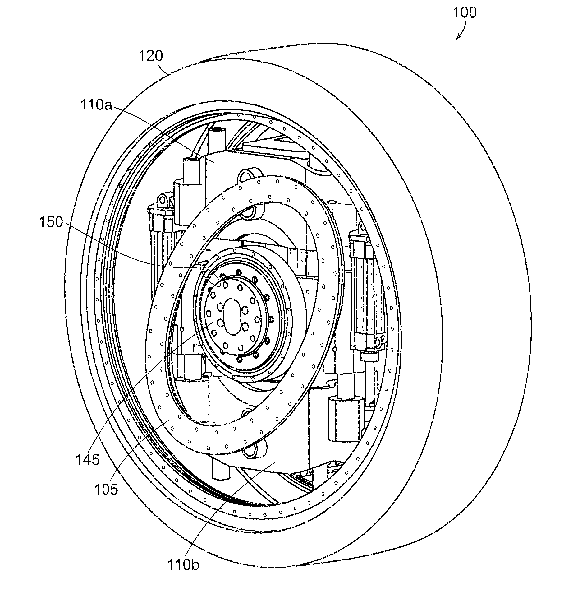
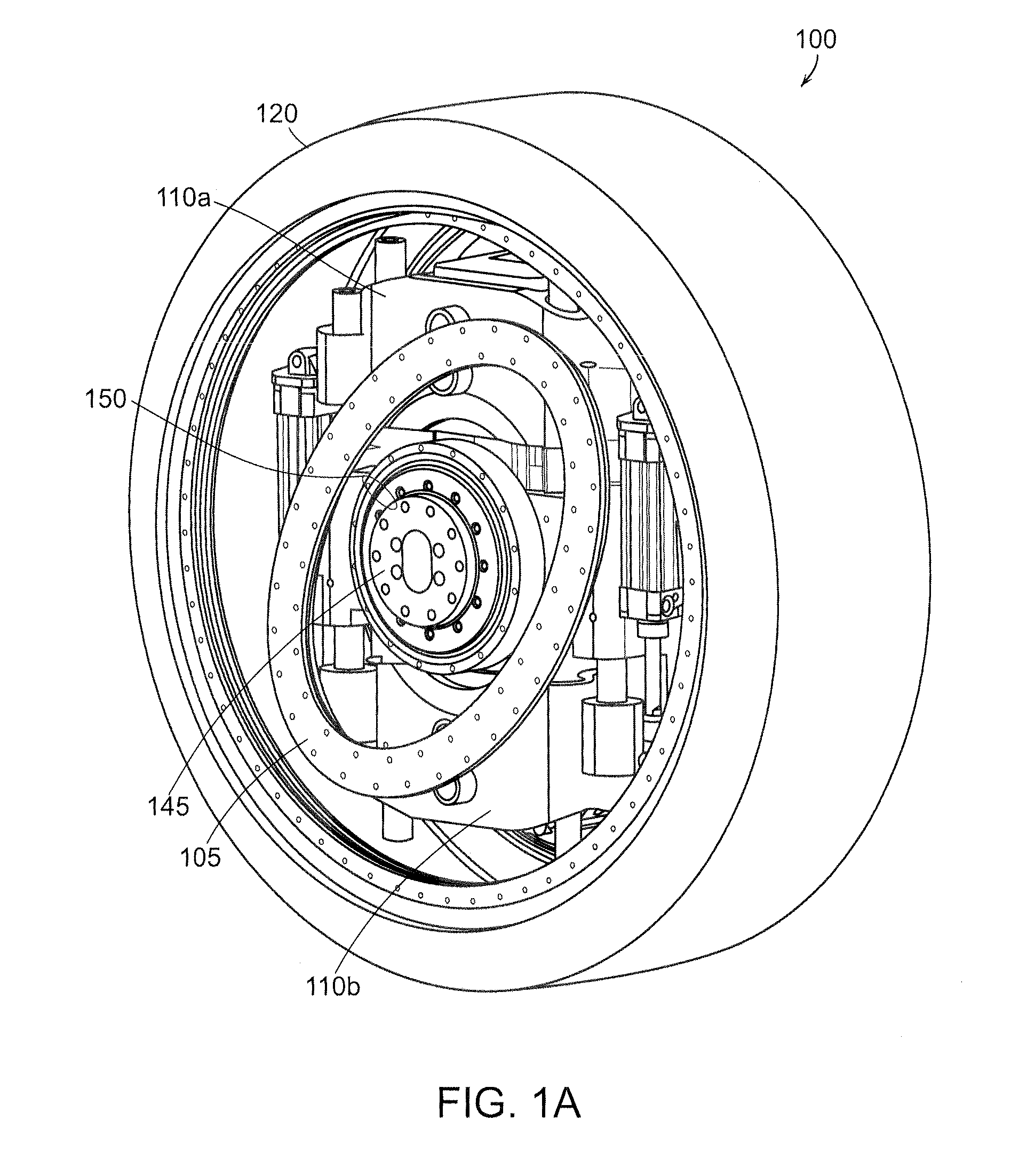
[0055]FIG. 1A shows an example rotary device 100 inside a wheel. The device includes a magnetic stator assembly 120, opposed electromagnetic actuators 110a, 110b, and a linear-to-rotary converter (e.g., cam) 105. The device may be attached to the chassis of a vehicle, for example, at a point on the far side of the wheel (not shown). The rotary device depicted inside the wheel may be attached to the wheel via the cam 105 using a circular plate, for example, which has been removed to show the inside of the wheel. Such a plate may be attached to both the rim of the wheel and the cam 105 using fasteners, such as bolts. The wheel and cam support plate rotate relative to a hub 145 about a bearing 150. It is important to note that the cam 105 is shown as an oval shape, but may take other forms, such as, for example, a cam having multiple lobes.

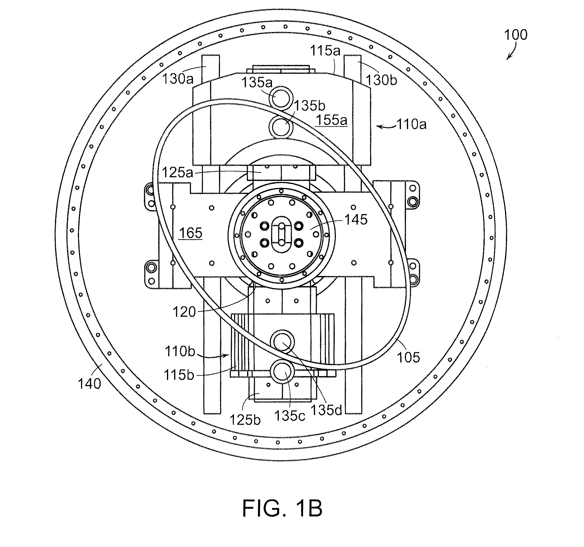
[0056]FIG. 1B shows the example rotary device 100 from the side of the wheel 140...


PUM


Abstract

A rotary and linear motion device includes a magnetic stator assembly, opposed electromagnetic actuators, and a linear-to-rotary converter (e.g., cam). Each electromagnetic actuator includes a coil that is configured to reciprocate relative to the magnetic stator assembly or to linearly translate in a common direction relative to the magnetic stator assembly. The electromagnetic actuators are coupled to the linear-to-rotary converter and upon reciprocation or linear translation, drive the linear-to-rotary converter in rotary or linear motion. The device may be located inside a wheel, which may be part of a vehicle. If part of a wheel of a vehicle, the device can be used to provide propulsion, steering, braking, and suspension for the vehicle.

Description

BACKGROUND OF THE INVENTION[0001]A motor in a vehicle is typically located in a central part of the vehicle, such as, for example, in front of the passenger compartment of the vehicle. Centrally-located motors drive the wheels of the vehicle via drive shafts, universal joints, and other components. Such motors may, for example, be fuel or electrically powered. Motors may also be located at or even in the wheels of a vehicle. These motors are known as hub motors and are typically electrically powered. A vehicle with four wheels may have, for example, four hub motors, one motor within each wheel.SUMMARY OF THE INVENTION[0002]With greater interest in electrically-powered vehicles, including hybrid vehicles, there is more interest in hub motors. However, hub motors suitable for vehicles have not previously been made available. A typical problem associated with a hub motor is that the primary mass of the motor is not suspended by the vehicle's suspension components and, therefore, contri...

Claims


Application Information

Patent Timeline
IPC IPC(8): B60K1/00H02K7/075H02K7/18B60L11/18H02K9/20
CPCB60G3/01H02K7/00B60G2202/40B60G2204/30B60G2300/60B60K7/0007B60K17/356B60K17/358B60K25/08B60K2007/0038B60K2007/0092H02K3/04H02K7/075H02K7/1876H02K15/0421H02K33/18H02K35/04B60G2300/50H02K33/00H02K7/06H02K35/00H02K7/065B60G17/02B60L2220/44B60L2220/50Y02T10/64
Inventor HUNTER, IAN W.
Owner INDIGO TECH INC
Why Eureka
Try Eureka