Brake device for a motor vehicle having at least three brake circuits

a technology of brake device and motor vehicle, which is applied in the direction of brake system, braking components, transportation and packaging, etc., can solve the problem of not being directly capable of being pressure-loaded by the brake pedal

Active Publication Date: 2011-05-12
ROBERT BOSCH GMBH
View PDF10 Cites 19 Cited by
  • Summary
  • Abstract
  • Description
  • Claims
  • Application Information

AI Technical Summary

Benefits of technology

[0016]An object of the present invention is providing a brake device for a motor vehicle, which supports even complex control processes related to braking and vehicle dynamics, has the highest reliability possible, and has a simple constructive design, if possible.

Problems solved by technology

The brake circuits of the second group are able to be run exclusively using a hydraulic pump, and are thus not directly capable of being pressure-loaded by a brake pedal having a brake cylinder.

Method used


Image

  • Brake device for a motor vehicle having at least three brake circuits
  • Brake device for a motor vehicle having at least three brake circuits
  • Brake device for a motor vehicle having at least three brake circuits

Examples


Embodiment Construction

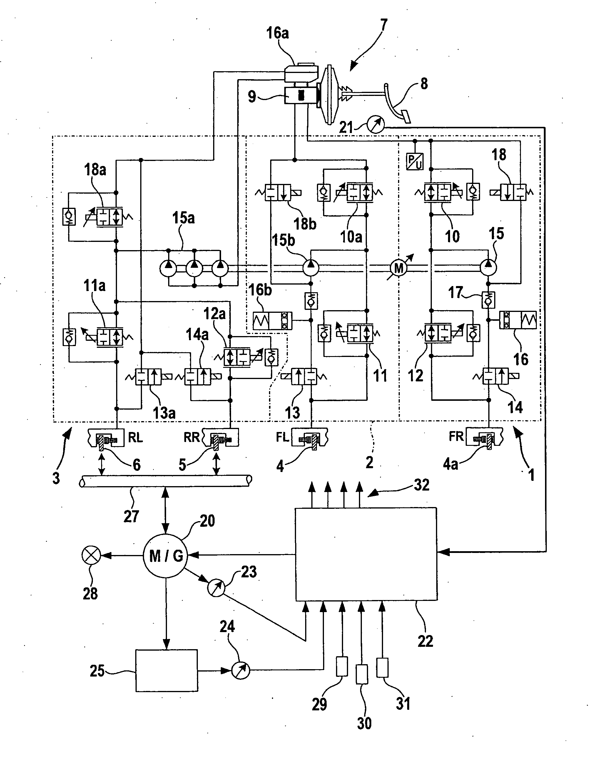
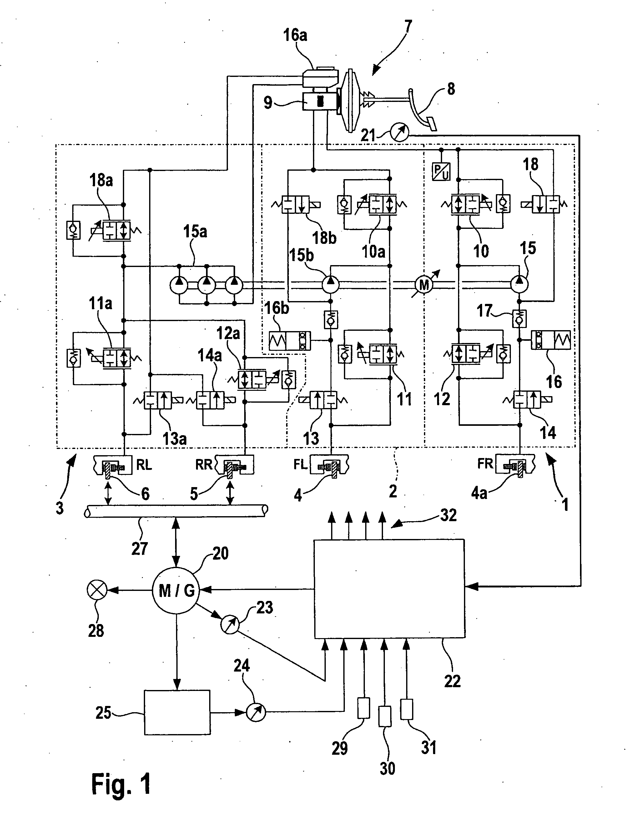
[0044]The brake device shown in FIG. 1 is similar in individual parts to a known standard modulating system having an active pressure-build-up. The front axle having left front wheel 4 and right front wheel 4a is equipped with two separate brake circuits, first brake circuit 1 and second brake circuit 2, of which each represents a completely modulation-capable braking system. Third brake circuit 3 is developed hydraulically, the same as first and second brake circuits 1, 2, and supplies in common the two rear wheel brakes of wheels 5, 6. The individual brake circuits are indicated by dotted lines. A common pump drive M is provided for hydraulic pumps 15, 15a, 15b of all three brake circuits, so that an active pressure build-up is able to take place in each brake circuit by itself. Individual braking effects on individual wheels can take place either by individual control of brake circuits 1, 2 of the first group or individual actuation of the wheel brakes of brake circuit 3 of the s...


PUM


Abstract

A brake device for motor vehicles has at least two hydraulic brake circuits which are directly connected to a master brake cylinder, as well as an additional brake circuit, which is able to be actuated via a control device, independently of the master brake cylinder. Because of the separate hydraulic brake circuits in the region of the front axle, redundancy is provided, while the third brake circuit, that is able to be actuated independently of the master brake cylinder and typically acts on the rear wheels, during automatic actuation, permits taking into account a braking effect by additional active assemblies, such as a driven generator.

Description

BACKGROUND OF THE INVENTION[0001]1. Field of the Invention[0002]The present invention relates to multi-circuit braking systems having hydraulic brake circuits for motor vehicles.[0003]2. Description of Related Art[0004]In the field of motor vehicle construction, hydraulic brakes have been customary for a long time because of their efficiency and their functional safety. Multi-circuit brake systems take care of a redundancy that still further increases functional safety, and these systems often have several hydraulic brake circuits acted upon by pressure from one or more master brake cylinders. The pressure is generated first by operating a brake pedal and is then reinforced, if necessary. Starting from the master brake cylinder, the wheel brakes have pressure applied to them and are operated thereby, often controlled by valves.[0005]It is also known that one may unload the brakes of a vehicle by additional deceleration elements. In this context, for example, an engine brake may be u...

Claims


Application Information

Patent Timeline
Patent Type & Authority Applications(United States)
IPC IPC(8): B60T13/74B60T7/12B60T1/08B60T8/24B60T8/17
CPCB60T8/1766B60T8/344B60T2270/608B60T8/4872B60T8/4072
Inventor WUERTH, GEBHARDMEHL, VOLKERKUNZ, MICHAELLEIBLEIN, MATTHIASQUIRANT, WERNER
Owner ROBERT BOSCH GMBH
Why Eureka
Try Eureka