

Molten salt fuels with high plutonium solubility
a technology of plutonium solubility and molten salt, which is applied in the direction of nuclear reactors, greenhouse gas reduction, uranium compounds, etc., can solve the problems of long-term sustainability and difficult to achieve the effect of long-term sustainability
- Summary
- Abstract
- Description
- Claims
- Application Information
AI Technical Summary
Problems solved by technology
Method used
Image

Examples
example 1
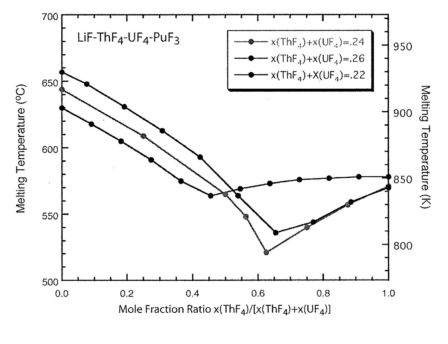
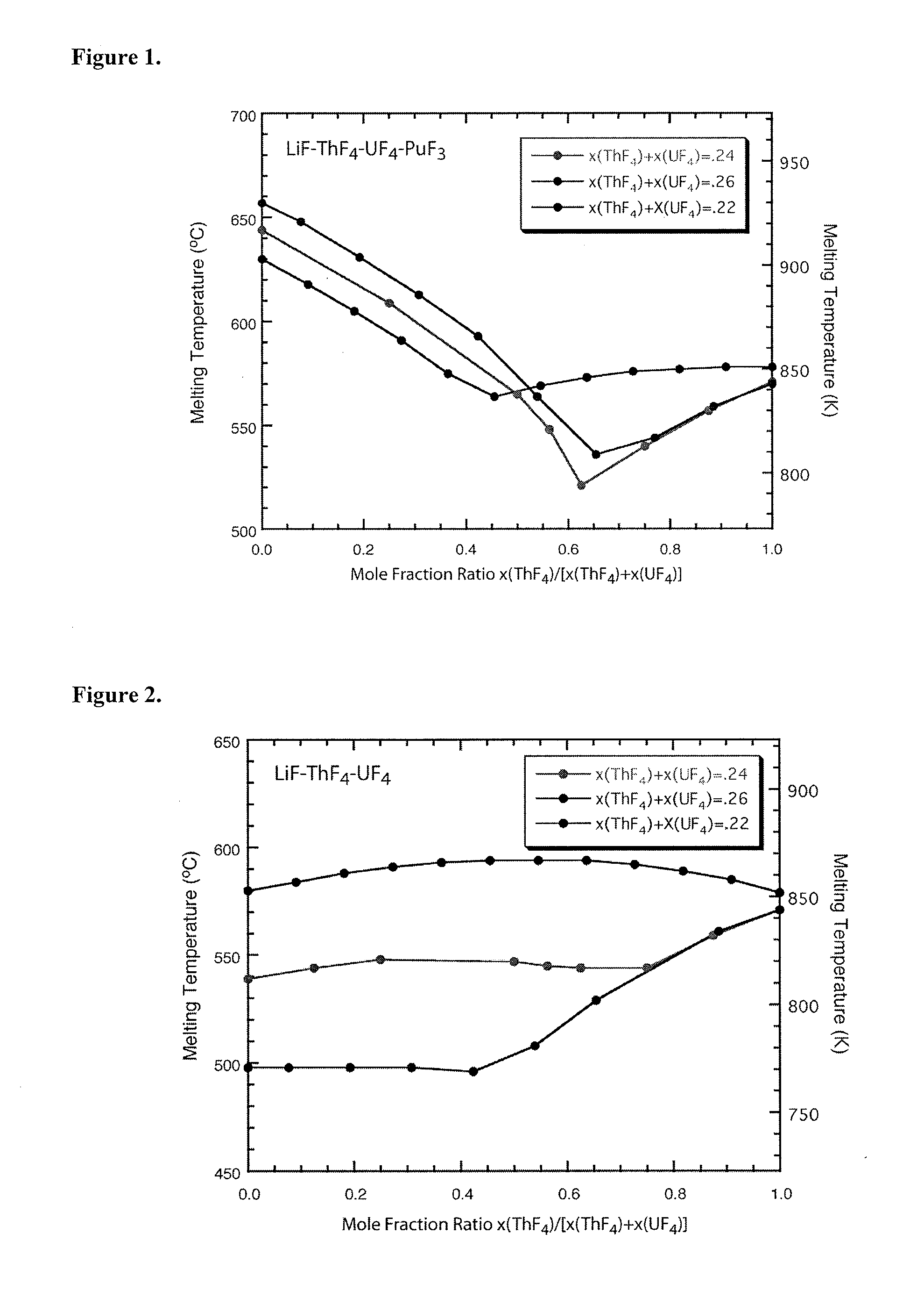
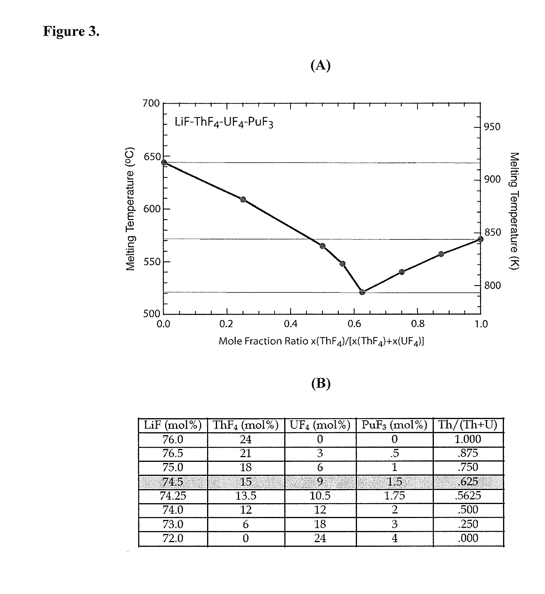
Preparation of LiF—UF4—ThF4—PuF3
[0033]The molten salt fuel can be prepared by first preparing the LiF—UF4—ThF4 salt according to the procedures in Shaffer, J. H. (1971), “Preparation and Handling of Salt Mixtures for the Molten Salt Reactor Experiment” (ORNL-4616), Oak Ridge National Laboratory, U.S. (published January 1971). ThF4 can be purchased commercially or produced by hydrofluorination of Th oxide or metal. The plutonium fuel is then provided as follows.
[0034]Excess weapons plutonium, which requires no preprocessing, is converted to the trifluoride by hydrofluorination in the presence of a small amount of hydrogen (i.e., probably 2) in the temperature range 500-600° C. The hydrogen prevents the formation of the tetrafluoride and the volatile hexafluoride. The PuF3 is mixed with LiF in the ratio 19.5 mol % PuF3-80.5 mol % 7LiF and heated above the eutectic temperature of 743° C. The mixture is cooled and stored for later use or injected in the fuel salt. If the mixture is coo...
PUM
 Abstract
Description
Claims
Application Information