Roof and gap fairing for the aerodynamic drag reduction of tanker trucks

a technology for tanker trucks and fairings, which is applied in the direction of roofs, transportation and packaging, vehicle arrangements, etc., can solve the problems of gap drag, increase aerodynamic drag, and increase fuel costs correspondingly, so as to reduce the amount of cross-stream flow, reduce the aerodynamic drag of semi-tankers, and smooth redirect flow

Inactive Publication Date: 2011-05-12
LAWRENCE LIVERMORE NAT SECURITY LLC
View PDF24 Cites 20 Cited by
  • Summary
  • Abstract
  • Description
  • Claims
  • Application Information

AI Technical Summary

Benefits of technology

[0009]One aspect of the present invention includes a fairing apparatus for reducing aerodynamic drag of a tanker truck in a freestream, the tanker truck of a type carrying a substantially cylindrical tank located behind a cab section with a gap therebetween, the fairing apparatus comprising: a fairing body having a roof section, and left and right side sections connected to and extending below left and right sides, respectively, of the roof section, said roof section having a roof fairing surface positively inclined towards a trailing end of the fairing body, and said left and right side sections having left and right side fairing surfaces, respectively, which diverge from each other towards the trailing end of the fairing body; and means for mounting the fairing body to the cab section so that the roof fairing surface is positively inclined from a roof surface of the cab section toward a top surface of the tank, and the left and right side fairing surfaces diverge from left and right side surfaces, respectively, of the cab section toward left and right side surfaces, respectively, of the tank, for streamlining the freestream transition across the gap.
[0013]In this manner, the roof fairing section compensates for the height mismatch between the cab and tanker by smoothly redirecting the flow from the cab roof onto the top of the tanker, and preventing the flow from entering into the gap from the cab roof. Similarly, the left and right fairing sections prevent the flow from entering into the gap from the cab sides, as well as compensating for the width mismatch between the cab and the tanker by smoothly redirecting the flow from the cab sides to the sides of the tank. Computational fluid dynamics simulations of a full-scale tractor and tanker have demonstrated that the roof and gap fairing decreases the amount of cross-stream flow in the gap and can significantly reduce the aerodynamic drag of the semi-tanker as the gap size is reduced.

Problems solved by technology

As the aerodynamic drag experienced by a vehicle increases, the fuel costs also correspondingly increase due to the greater energy required to overcome the drag.
This mismatch between the profiles of the cab section and the tank can increase aerodynamic drag by direct flow impingement in the freestream.
Both of these pressure changes produce gap drag.
However, because the axle loading of the tractor is fixed by the load distribution of the tanker trailer, reducing the gap size cannot be achieved by simply moving the tanker trailer closer to the cab base.

Method used


Image

  • Roof and gap fairing for the aerodynamic drag reduction of tanker trucks
  • Roof and gap fairing for the aerodynamic drag reduction of tanker trucks
  • Roof and gap fairing for the aerodynamic drag reduction of tanker trucks

Examples


Embodiment Construction

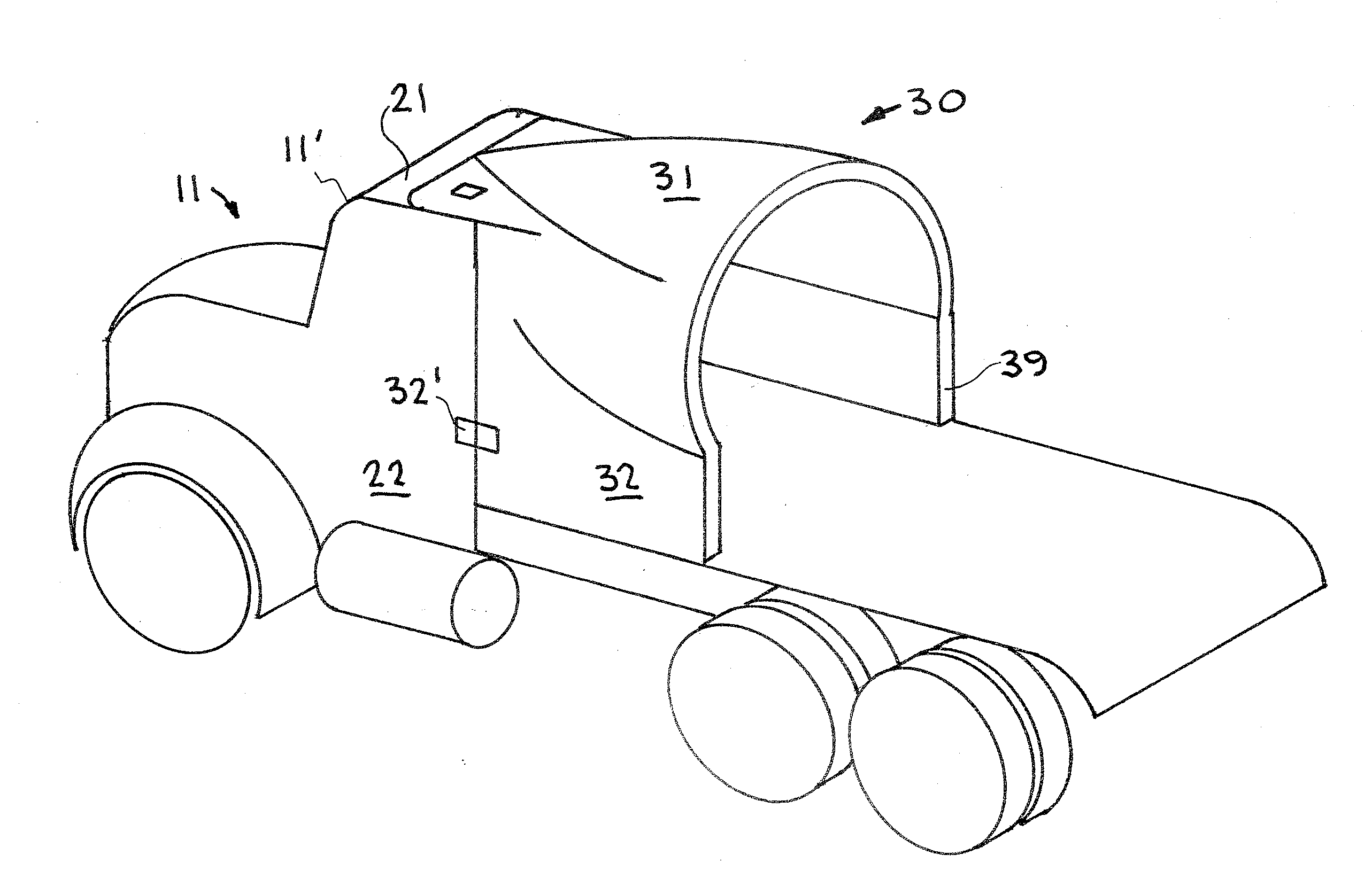
[0025]Turning now to the drawings, FIGS. 4-8 show an exemplary first embodiment of the fairing apparatus of the present invention for reducing aerodynamic drag of tanker trucks in a freestream. In particular, the fairing apparatus includes a fairing body 30 having a roof section 31, and left and right side sections 32 and 39, respectively. The roof section 31 is shown having a leading end 33 and a trailing end 34, and the left and right side sections are each shown having a leading end 35 and a trailing end 36. The trailing ends 34 and 36 are shown aligned with each other and may be considered the trailing end of the fairing body, while the leading end 33 of the roof section is shown at a forward position relative to the leading end 35 of the left / right side sections. In the alternative, it may be appreciated that the leading ends 33 and 35 may also be aligned with each other similar to the trailing ends 34, 36. In any case, the left and right side sections are connected to and exte...


PUM


Abstract

A fairing apparatus for reducing aerodynamic drag of a tanker in a freestream, and including a fairing body with a roof section, and left and right side sections connected to and extending below the roof section. Fasteners, for example, mount the fairing body on a cab of the tanker so that the roof, left, and right side sections extend from the roof, left and right side surfaces, respectively, of the cab towards a cylindrical tank carried behind the cab to reduce the gap between the cab and the tank and impede cross-flow therethrough, and the fairing surfaces of the roof, left, and right side sections are angled and preferably curvilinearly contoured to redirect airflow from the top and side surfaces of the cab to the curvilinearly contoured top and side surfaces of the tank to compensate for a profile mismatch between the cab and the taller and / or wider tank.

Description

CLAIM OF PRIORITY IN PROVISIONAL APPLICATION[0001]This application claims the benefit of U.S. provisional application No. 61 / 260,266 filed Nov. 11, 2009, entitled, “Aerodynamics of a Cryogenic Semi-Tanker” by Jason Ortega et al, incorporated by reference herein.FEDERALLY SPONSORED RESEARCH OR DEVELOPMENT[0002]The United States Government has rights in this invention pursuant to Contract No. DE-AC52-07NA27344 between the United States Department of Energy and Lawrence Livermore National Security, LLC for the operation of Lawrence Livermore National Laboratory.FIELD OF THE INVENTION[0003]The present invention relates to aerodynamic drag reduction methods and devices. The invention relates more particularly to a roof and gap fairing apparatus for reducing the aerodynamic drag of tanker trucks having a substantially cylindrical tank behind a cab section with a gap therebetween.BACKGROUND OF THE INVENTION[0004]It is well known in the art of vehicle design that the fuel consumption of a v...

Claims


Application Information

Patent Timeline
Patent Type & Authority Applications(United States)
IPC IPC(8): B62D35/00
CPCB62D35/001
Inventor SALARI, KAMBIZORTEGA, JASON M.
Owner LAWRENCE LIVERMORE NAT SECURITY LLC
Why Eureka
Try Eureka