
Stereoscopic liquid crystal display device having touch panel and method for manufacturing the same

a liquid crystal display and touch panel technology, applied in the field of liquid crystal display devices, can solve the problems of noise in a specific section, parasitic capacitance may occur between, and malfunction of touch detection, and achieve the effect of stably detecting touch

Active Publication Date: 2011-05-12
LG DISPLAY CO LTD
View PDF6 Cites 72 Cited by
  • Summary
  • Abstract
  • Description
  • Claims
  • Application Information

AI Technical Summary

Benefits of technology

[0036]Another object of the present invention is to provide a stereoscopic liquid crystal display device having a touch panel and a method for manufacturing the same that can stably detect a touch without any influence from a neighboring display panel or an operation of an electrically-driven liquid crystal lens.

Problems solved by technology

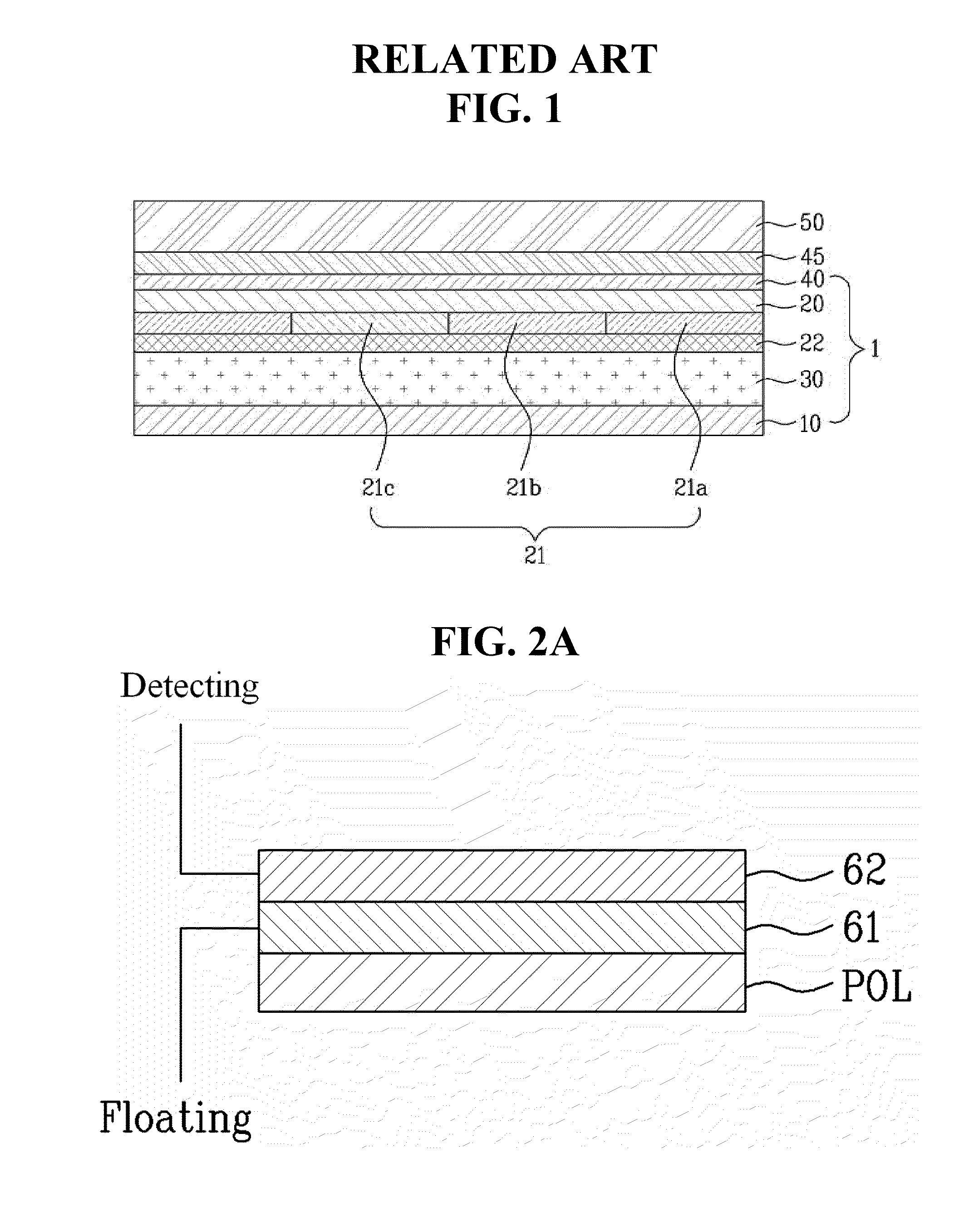
Therefore, when the above-described resistive or capacitive touch panel is positioned on the liquid crystal panel, a parasitic capacitance may occur between a transparent electrode within the touch panel and a common electrode of the liquid crystal panel.
Therefore, in a structure fixing a touch panel on a liquid crystal panel provided with a rear electrode, since it is not yet possible to completely and fully prevent a parasitic capacitance or noise caused by the liquid crystal panel from occurring, efforts are being made in order to implement a solution to such problems.
For example, in case of a capacitive or resistive touch panel, a parasitic capacitance may occur between a transparent electrode provided in the touch panel and a common electrode provided in the liquid crystal panel, and such parasitic capacitance may be recognized as noise, thereby causing a malfunction in the touch detection.
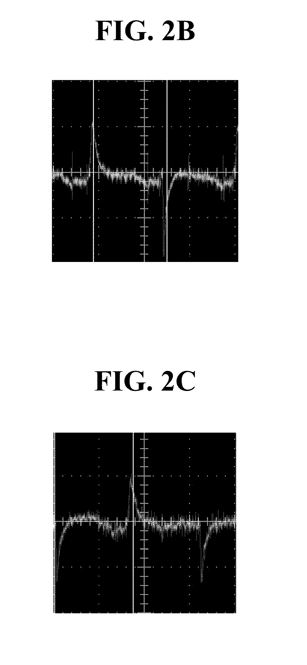
Also, even when a rear electrode is provided on a rear surface side of a liquid crystal panel in order to block (or prevent) any influence caused by the liquid crystal panel, a noise may occur in a specific section even when no touch has occurred.
And, in case the touch panel is positioned above the liquid crystal panel, there may be difficulty in that the touch panel cannot fully and completely block (or prevent) influence caused by the liquid crystal panel.
Thus, increasing the fabrication (or manufacturing) cost for forming the display device having complex functions.

Method used


Image

  • Stereoscopic liquid crystal display device having touch panel and method for manufacturing the same
  • Stereoscopic liquid crystal display device having touch panel and method for manufacturing the same
  • Stereoscopic liquid crystal display device having touch panel and method for manufacturing the same

Examples


Embodiment Construction

[0054]Reference will now be made in detail to the preferred embodiments of the present invention, examples of which are illustrated in the accompanying drawings. Wherever possible, the same reference numbers will be used throughout the drawings to refer to the same or like parts.

[0055]Hereinafter, the stereoscopic liquid crystal display device having a touch panel and a method of manufacturing the same will now be described in detail with reference to the accompanying drawings.

[0056]FIG. 3 illustrates a general cross-sectional view of a stereoscopic liquid crystal display device having a touch panel according to the present invention.

[0057]Referring to FIG. 3, the stereoscopic liquid crystal display device having a touch panel according to the present invention consists of a liquid crystal panel 100 including a first substrate 110 and a second substrate 120 facing into each other and first liquid crystal layer 130 filling a space between the first substrate 110 and the second substr...


PUM


Abstract

A stereoscopic liquid crystal display device having a touch panel and a method for manufacturing the same, wherein a stable touch detection can be performed without influencing the operation of a neighboring display panel or an electrically-driven liquid crystal lens, are disclosed.

Description

[0001]This application claims the benefit of the Korean Patent Application No. 10-2009-0109193, filed on Nov. 12, 2009, which is hereby incorporated by reference as if fully set forth herein.BACKGROUND OF THE INVENTION[0002]1. Field of the Invention[0003]The present invention relates to a liquid crystal display device and, more particularly, to a stereoscopic liquid crystal display device having a touch panel and a method for manufacturing the same, wherein a stable touch detection can be performed without influencing the operation of a neighboring display panel or an electrically-driven liquid crystal lens.[0004]2. Discussion of the Related Art[0005]Recently, as the world has reached a full-scale information age, the field of display that can visually express electric information signals has developed at a vast rate. And, in order to meet with the requirements of such development, various types of flat display devices having excellent functions and characteristics, such as compact ...

Claims


Application Information

Patent Timeline
IPC IPC(8): G06T15/00
CPCG02F1/13338G06F2203/04103G06F2203/04107G06F3/0412H04N13/0454G02B27/22H04N13/0404H04N13/305H04N13/359G02B30/00
Inventor SON, JUNG-EUNLEE, JOUN-HO
Owner LG DISPLAY CO LTD
Learn More