
Backlight and display device using the same

Inactive Publication Date: 2011-05-12
SHARP KK
View PDF16 Cites 23 Cited by
  • Summary
  • Abstract
  • Description
  • Claims
  • Application Information

AI Technical Summary

Benefits of technology

[0015]In accordance with the present invention, it is possible to obtain a backlight, as well as a display device, that can be expected to operate in a stable manner because circuit components, including light emitting elements, are prevented from undergoing temperature-induced degradation.

Problems solved by technology

However, due to the fact that light emitting diodes have the property of emitting heat when driven, the temperature of the backlight as a whole increases when the backlight is operated.

Method used


Image

  • Backlight and display device using the same
  • Backlight and display device using the same
  • Backlight and display device using the same

Examples


embodiment 1

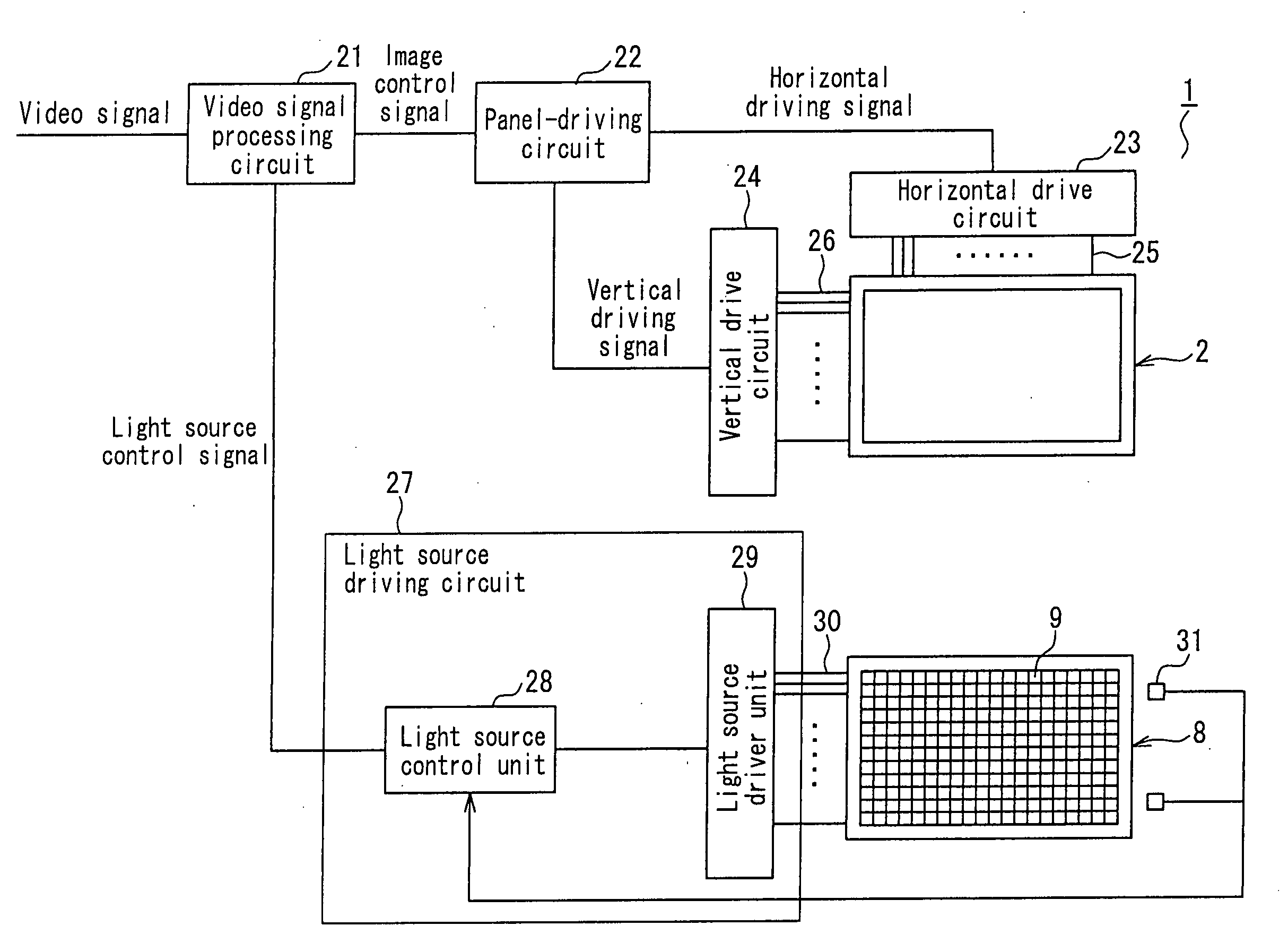
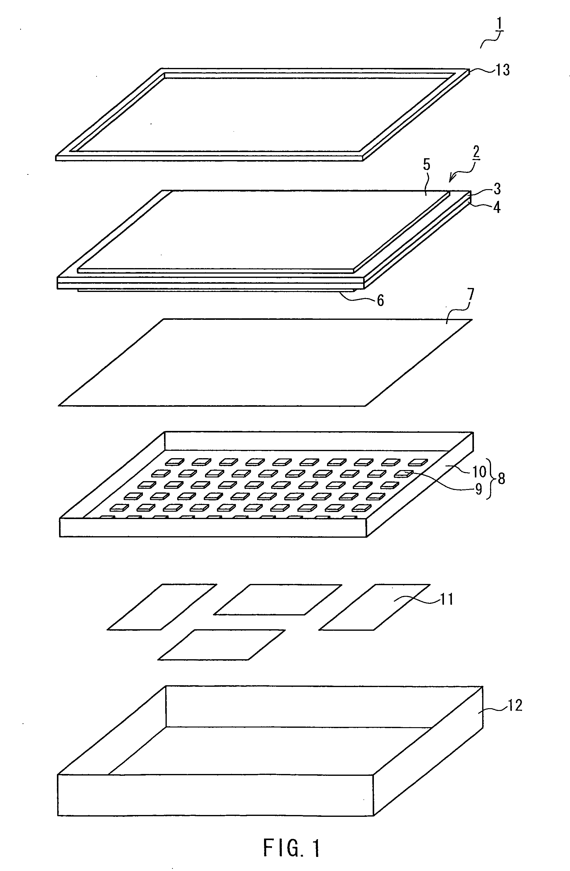
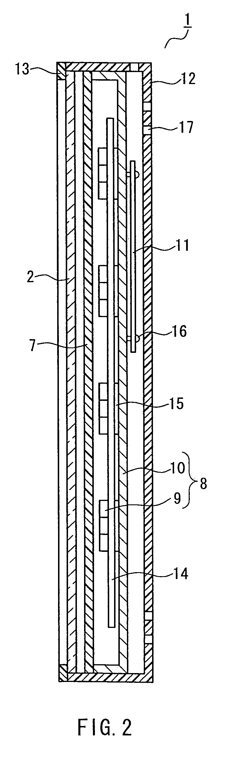
[0043]FIG. 1 is an exploded oblique view that schematically illustrates the configuration of a display device according to an embodiment of the present invention. As shown in FIG. 1, the liquid crystal display device 1 according to the present embodiment has a liquid crystal panel 2 that serves as a display unit; a backlight 8 that emits light necessary for displaying images on this liquid crystal panel 2; an optical sheet 7 that improves the uniformity of illumination by diffusing and collecting the illumination emitted from the backlight 8; circuit boards 11 arranged on the rear face of the backlight 8; a rear cover 12 that has incorporated therein the above-mentioned components, from the liquid crystal panel 2 to the circuit boards 11; and a bezel 13 that is arranged on the front face of the liquid crystal panel 2 and serves as a front cover.

[0044]The liquid crystal panel 2 is a transmissive display element that displays images by controlling the amount of light transmitted throu...

embodiment 2

[0107]Next, explanations will be provided with respect to a second embodiment of the inventive liquid crystal display device, which is a display device equipped with a backlight capable of preventing light emitting elements and other circuit components from undergoing degradation due to operation under elevated temperature conditions when the circuit boards acting as heat sources are not identified or when the way the temperature of the chassis 10 of the backlight 8 increases varies depending on the actual conditions of use.

[0108]It should be noted that while a liquid crystal display device is used as an example to describe the display device in the present embodiment, the basic configuration of the display device, with the exception of the placement of the temperature sensors in the backlight and the way the light source control unit of the light source-driving circuit operates based on the temperature measurements detected by the temperature sensors, is identical to that of the li...


PUM


Abstract

A backlight is provided that can prevent light emitting elements and other circuit components from undergoing degradation due to temperature elevation during backlight operation. A display device utilizing the backlight is also provided. In at least one example embodiment, the backlight is a backlight that is provided on the rear side of a display unit and projects illumination used for displaying images onto the display unit, the backlight including: multiple light emitting elements arranged in a single plane; a light source driving circuit having a light source control unit that defines the value of the drive power applied to each light emitting element and a light source driver unit that applies drive power corresponding to the value defined by the light source control unit to the light emitting elements; and temperature sensors that detect the ambient temperature of the regions where the light emitting elements that attain the highest temperatures during operation are disposed, wherein the light source control unit reduces the drive power applied to the light emitting elements that attain the highest temperatures during operation when the output values of the temperature sensors exceed a predetermined threshold value.

Description

TECHNICAL FIELD[0001]The present invention relates to a backlight that emits illumination used for displaying images on a display unit, as well as to a display device that utilizes such a backlight, and, in particular, it relates to a backlight and a display device that can prevent light emitting elements, i.e. the light sources, as well as other circuit components, from undergoing degradation due to an increase in temperature during operation.BACKGROUND ART[0002]In recent years, liquid crystal display devices, which feature low power consumption, thin profile, light weight, and other advantages, have been widely used in television receivers and other display devices. The liquid crystal panels used in the display units of liquid crystal display devices are non-emitting display elements, in other words, they do not emit light by themselves. Accordingly, liquid crystal display devices are typically provided with an illumination device called a backlight, which is disposed on the rear ...

Claims


Application Information

Patent Timeline
IPC IPC(8): G09G3/36G09G5/10G09F13/08
CPCG02F1/133602G02F1/133603G02F2001/133612G09G2320/041G09G3/3426G09G2320/0233G02F2001/133628G02F1/133612G02F1/133628
Inventor TAKEDA, DAISUKE
Owner SHARP KK
Features
  • Generate Ideas
  • Intellectual Property
  • Life Sciences
  • Materials
  • Tech Scout
  • Unparalleled Data Quality
  • Higher Quality Content
  • 60% Fewer Hallucinations
Learn More