

Laser microscope using phase-modulation type spatial light modulator
a laser microscope and spatial light technology, applied in the field of laser microscopes, can solve the problems of low light use intensity and low density of light applied to objects
- Summary
- Abstract
- Description
- Claims
- Application Information
AI Technical Summary
Problems solved by technology
Method used
Image

Examples
embodiment 1
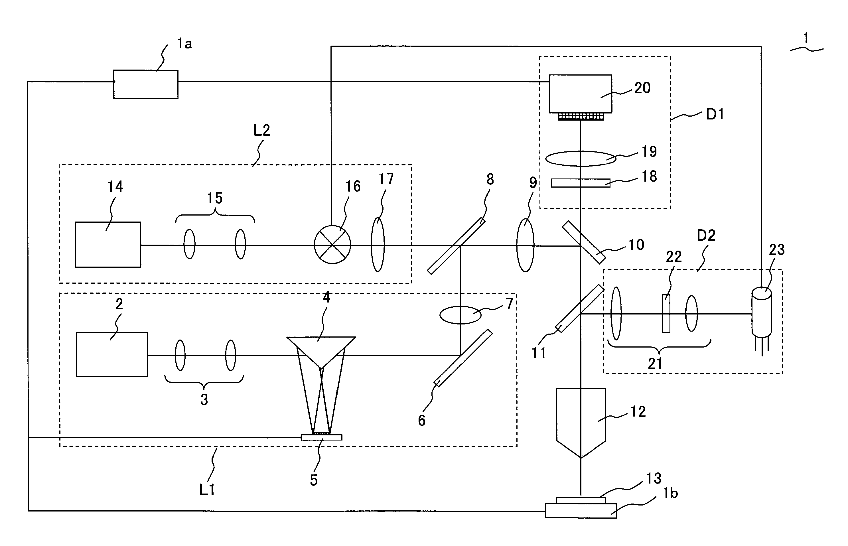
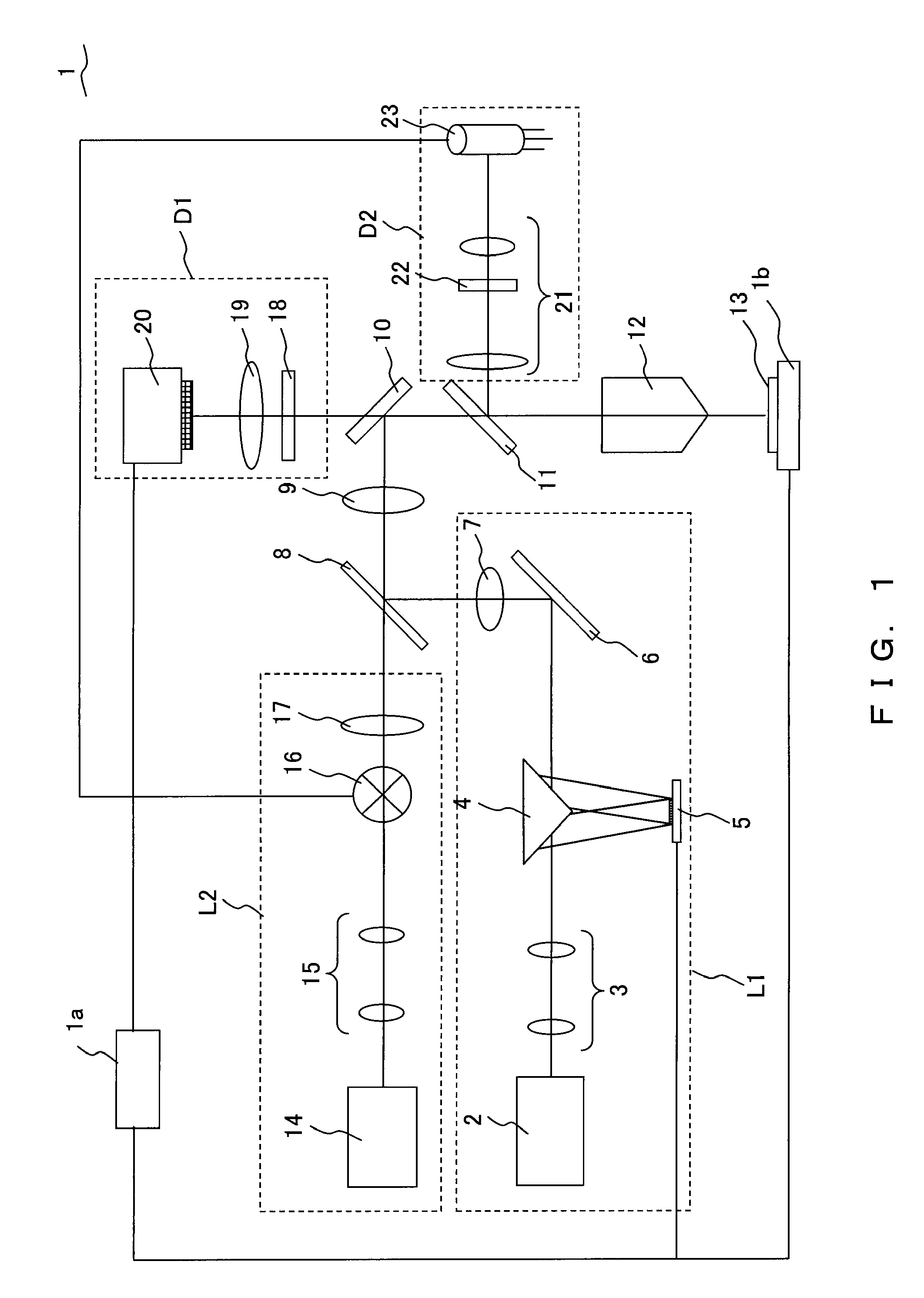
FIG. 1 is a conceptual diagram illustrating the configuration of a laser microscope according to the present embodiment. A laser microscope 1 is a two-photon excitation microscope that excites a sample 13 using a two-photon process by ultra-short pulse laser light (illumination light) in the infrared territory emitted from a titanium-sapphire laser being a laser light source.
First, the configuration of the laser microscope 1 according to the present embodiment is explained.
The laser microscope 1 is configured including a control unit 1a, a first lighting unit L1, a second lighting unit L2, a dichroic mirror 8, a tube lens 9, a dichroic mirror 10, a dichroic mirror 11, an objective 12 that applies laser light on the sample 13, a stage 1b on which the sample 13 is placed and that moves in the direction of the optical axis of the objective 12, a first detection unit D1, and a second detection unit D2.
The first lighting unit L1 is a lighting unit that applies light of a desired pattern ...
embodiment 2
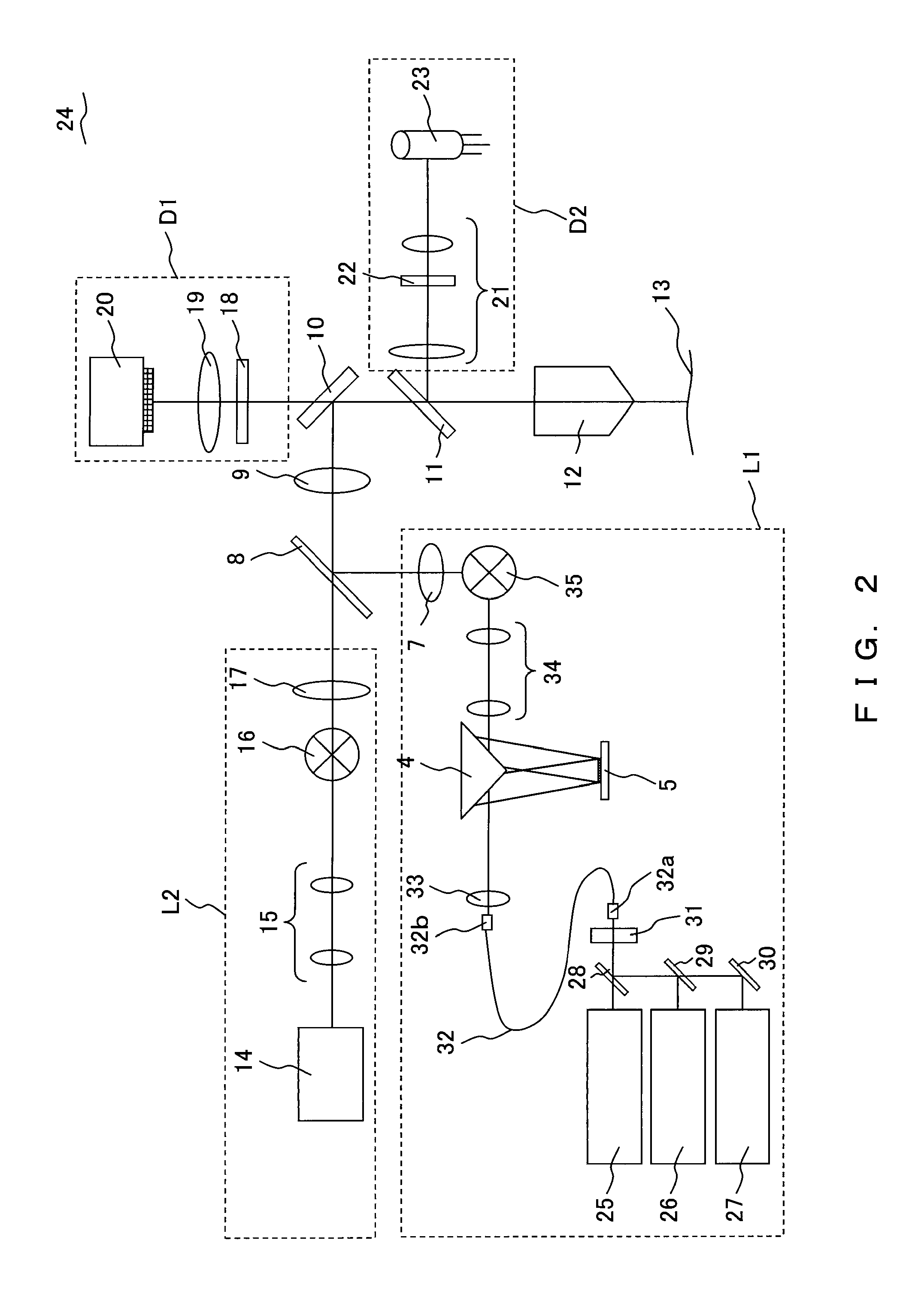
FIG. 2 is a conceptual diagram illustrating the configuration of a laser microscope according to the present embodiment.
In a laser microscope 24 according to the present embodiment, the configuration of the first lighting unit L1 is different from that for the laser microscope 1. Since the other configurations are the same as in the laser microscope 1, the same numerals are attached and description is omitted. Meanwhile, while the laser microscope 24 has a control unit and a stage in the same manner as the laser microscope 1, these are omitted in FIG. 2.
The first lighting unit L1 of the laser microscope 24 includes, instead of the titanium sapphire laser 2 and the beam expander 3, a plurality of visible laser light sources (laser 25, laser 26, laser 27) that respectively emit laser light of a different wavelength, a dichroic mirror 28, a dichroic mirror 29, a mirror 30, an acoustic optical modulator (hereinafter, referred to as AOM) 31, a single mode optical fiber 32, and a collimat...
embodiment 3
FIG. 4 is a conceptual diagram illustrating the configuration of a laser microscope according to the present embodiment.
Many of the constituent elements of a laser microscope 37 according to the present embodiment are the same as in the laser microscope 1 (or a laser microscope 24). For this reason, the same numerals are given to the same constituent elements, and description is omitted. Meanwhile, while the laser microscope 37 has a control unit and a stage as well as the laser microscope 1, these are omitted in FIG. 4.
The laser microscope 37 is configured including a first lighting unit L1, the second lighting unit L2, a turret 47 having dichroic mirrors (dichroic mirror 47a, dichroic mirror 47b), the tube lens 9, the dichroic mirror 10, the dichroic mirror 11, the objective 12 that applies laser light on the sample 13, the first detection unit D1, the second detection unit D2, the third detection unit D3 and the fourth detection unit D4. The first lighting unit L1 includes the pu...
PUM
 Abstract
Description
Claims
Application Information