
Printed circuit board and fuel cell

a printed circuit board and fuel cell technology, applied in the field of printed circuit boards and fuel cells, can solve the problem that fuel leakage cannot be reliably prevented, and achieve the effect of reliably preventing fuel leakage and a fuel cell including

Inactive Publication Date: 2011-05-12
NITTO DENKO CORP
View PDF15 Cites 11 Cited by
  • Summary
  • Abstract
  • Description
  • Claims
  • Application Information

AI Technical Summary

Benefits of technology

[0008]An object of the present invention is to provide a printed circuit board capable of reliably preventing fuel leakage and a fuel cell including the same.
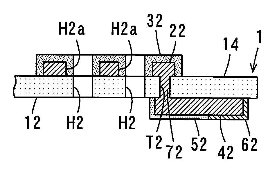
[0012]In this case, since the drawn-out conductor portion is provided on the other surface of the insulating layer, the seal member reliably adheres to the region for sealing of the insulating layer. This suppresses formation of clearance between the seal member and the insulating layer. Accordingly, the fuel is reliably inhibited from leaking out of the seal member. This reliably prevents fuel leakage from the fuel cell and output reduction of the fuel cell.
[0014]In this case, the collector portion and the drawn-out conduction portion are electrically connected to each other through the plurality of first holes, thus improving electrical conductivity between the collector portion and the drawn-out conductor portion. This improves characteristics of the fuel cell using the printed circuit board.
[0020]In this case, since the drawn-out conductor portions are provided on the other surfaces of the insulating layers, the seal member reliably adheres to the regions for sealing of the insulating layers of the first and second boards. This suppresses formation of clearance between the seal member and the insulating layer of the first board and between the seal member and the insulating layer of the second board. Accordingly, the fuel is reliably inhibited from leaking out of the seal member. This reliably prevents fuel leakage from the fuel cell and output reduction of the fuel cell.
[0024]In this case, since the drawn-out conductor portions are provided on the other surfaces of the insulating layers, the seal members reliably adhere to the regions for sealing of the insulating layers of the first and second boards in the first and second boards. This suppresses formation of clearance between the seal member and the insulating layer of the first board and between the seal member and the insulating layer of the second board. Accordingly, the fuel is reliably inhibited from leaking out of the seal member. This reliably prevents fuel leakage from the fuel cell and output reduction of the fuel cell.
[0025]According to the present invention, fuel leakage from the fuel cell is reliably prevented. As a result, output reduction of the fuel cell is reliably inhibited.

Problems solved by technology

However, fuel leakage cannot reliably be prevented with the configuration described in JP 2004-200064 A.

Method used


Image

  • Printed circuit board and fuel cell
  • Printed circuit board and fuel cell
  • Printed circuit board and fuel cell

Examples


first embodiment

(1) First Embodiment

(1-1) Configuration of Printed Circuit Board

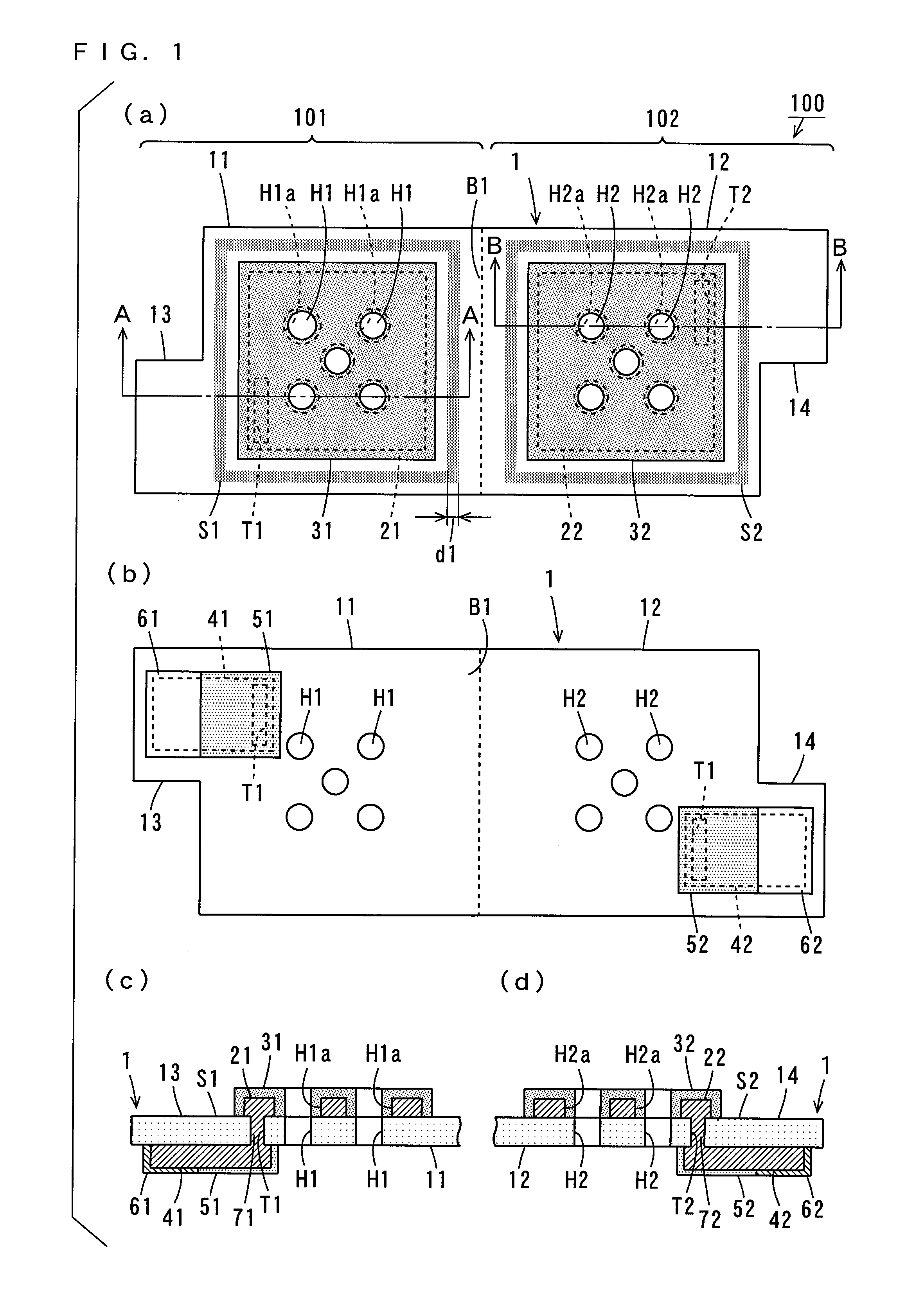
[0036]FIG. 1 shows a plan view and a sectional view of a printed circuit board according to a first embodiment. FIG. 1 (a) shows one surface of the printed circuit board, and FIG. 1 (b) shows the other surface of the printed circuit board. FIG. 1 (c) shows a sectional view taken along the line A-A of FIG. 1 (a), and FIG. 1 (d) shows a sectional view taken along the line B-B of FIG. 1 (a).

[0037]As shown in FIG. 1 (a), the printed circuit board 100 includes a base insulating layer 1 made of polyimide, for example. The base insulating layer 1 includes a first insulating portion 11, a second insulating portion 12, a third insulating portion 13 and a fourth insulating portion 14 each having a rectangular shape. The first insulating portion 11 and the second insulating portion 12 have the same shape and size, and the third insulating portion 13 and the fourth insulating portion 14 have the same shape and size.

[0038]The first ...

second embodiment

(2) Second Embodiment

[0079]Description is made of a printed circuit board according to a second embodiment while referring to differences from the above-described first embodiment.

[0080]FIG. 5 shows a plan view and a sectional view showing part of the printed circuit board according to the second embodiment. FIG. 5 (a) shows the configurations of the top surfaces of the first insulating portion 11 and the third insulating portion 13, and FIG. 5 (b) shows a cross section taken along the line C-C of FIG. 5 (a). The configurations of the top surfaces and the back surfaces of the second insulating portion 12 and the fourth insulating portion 14 are the same as those of the first insulating portion 11 and the third insulating portion 13 shown in FIG. 5.

[0081]As shown in FIGS. 5 (a) and (b), the drawn-out conductor portion 41 is formed to extend to a position in proximity to the bend portion B1 in the printed circuit board 100a according to the present embodiment. Openings H11a each havin...

third embodiment

(3) Third Embodiment

[0084]Description is made of a printed circuit board according to a third embodiment while referring to differences from the above-described second embodiment.

[0085]FIG. 6 shows a plan view and a sectional view showing part of the printed circuit board according to the third embodiment. FIG. 6 (a) shows the configurations of the top surfaces of the first insulating portion 11 and the third insulating portion 13, and FIG. 6 (b) shows a cross section taken along the line D-D of FIG. 6 (a). The configurations of the top surfaces and the back surfaces of the second insulating portion 12 and the fourth insulating portion 14 are the same as those of the first insulating portion 11 and the third insulating portion 13 shown in FIG. 6.

[0086]As shown in FIG. 6, a plurality of (three in this example) holes T1 and the connecting layers 71 are formed in portions of the first insulating portion 11 between the collector portion 21 and the drawn-out conductor portion 41 in the p...


PUM


Abstract

A rectangular collector portion is formed on each of a first insulating portion and a second insulating portion. A cover layer is provided on the first insulating portion to cover the collector portion, and a cover layer is provided on the second insulating portion to cover the collector portion. A seal region is provided on the first insulating portion to surround the cover layer. A seal region is provided on the second insulating portion to surround the cover layer. Rectangular drawn-out conductor portions are formed on the back surface of the base insulating layer. The collector portion and the drawn-out conductor portion are electrically connected to each other, and the collector portion and the drawn-out conductor portion are electrically connected to each other.

Description

BACKGROUND OF THE INVENTION[0001]1. Field of the Invention[0002]The present invention relates to a printed circuit board and a fuel cell using the same.[0003]2. Description of the Background Art[0004]Batteries that are small in size and have high capacity are desired for mobile equipment such as cellular telephones. Therefore, fuel cells capable of providing higher energy density than conventional batteries such as lithium secondary batteries have been developed. Examples of the fuel cells include a direct methanol fuel cell.[0005]In the direct methanol fuel cell, methanol is decomposed by a catalyst, forming hydrogen ions. The hydrogen ions are reacted with oxygen in the air to generate electrical power. In this case, chemical energy can be converted into electrical energy with extremely high efficiency, so that significantly high energy density can be obtained.[0006]A flexible printed circuit board (hereinafter abbreviated as a printed circuit board), for example, is provided as a...

Claims


Application Information

Patent Timeline
IPC IPC(8): H01M2/00H05K1/11H05K1/14
CPCH01M8/0269H01M8/1011H05K1/0272H05K1/0393H05K1/16Y02E60/50H05K2201/056H05K2201/09063H05K2201/09481Y02E60/523H05K3/244
Inventor HANAZONO, HIROYUKI
Owner NITTO DENKO CORP
Learn More