Power control panel, system and method

a power control panel and power control technology, applied in the field of electric power control systems, can solve the problems of not being able to properly control the power supply of the circuit board, not being able to operate the circuit breaker manually as a switch control, and not being able to achieve the effect of convenient installation and affordable us

Active Publication Date: 2011-05-12
LEO WHITE LLC
View PDF24 Cites 12 Cited by
  • Summary
  • Abstract
  • Description
  • Claims
  • Application Information

AI Technical Summary

Benefits of technology

[0014]It is an object of the present invention to provide a system and method tha

Problems solved by technology

Circuit breakers found in conventional circuit panel boards are typically not designed for switching purposes.
Operating those circuit breakers manually as a means of switch control is not recommended by the manufacturers and certainly not a realistic means of proper energy management.
Improperly configured building/energy management systems are believed to account for 20% of building energy usage, or approximately 8% of total energy usage in the United States.
The integrated software components are complex, often proprietary in nature and expensive to install in o

Method used


Image

  • Power control panel, system and method
  • Power control panel, system and method
  • Power control panel, system and method

Examples


Embodiment Construction

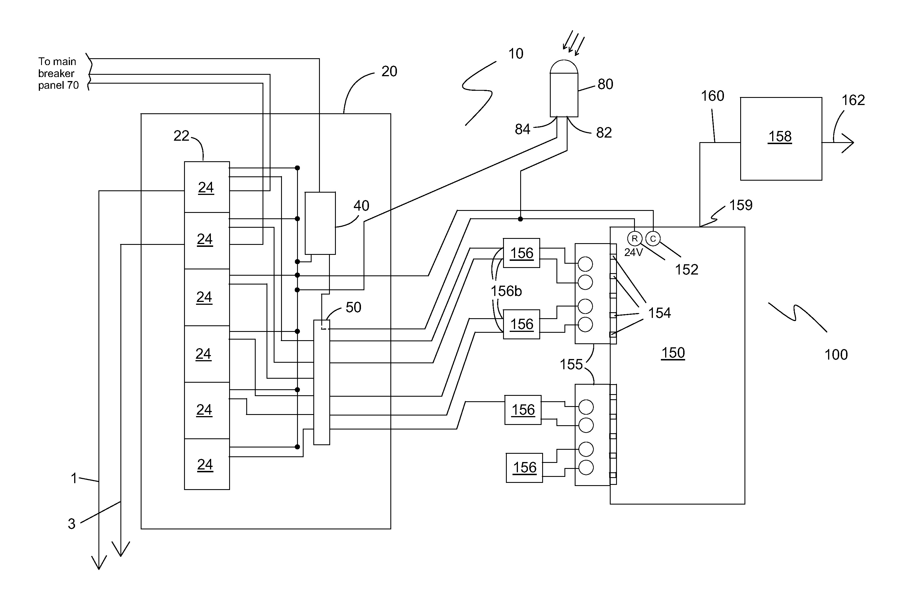
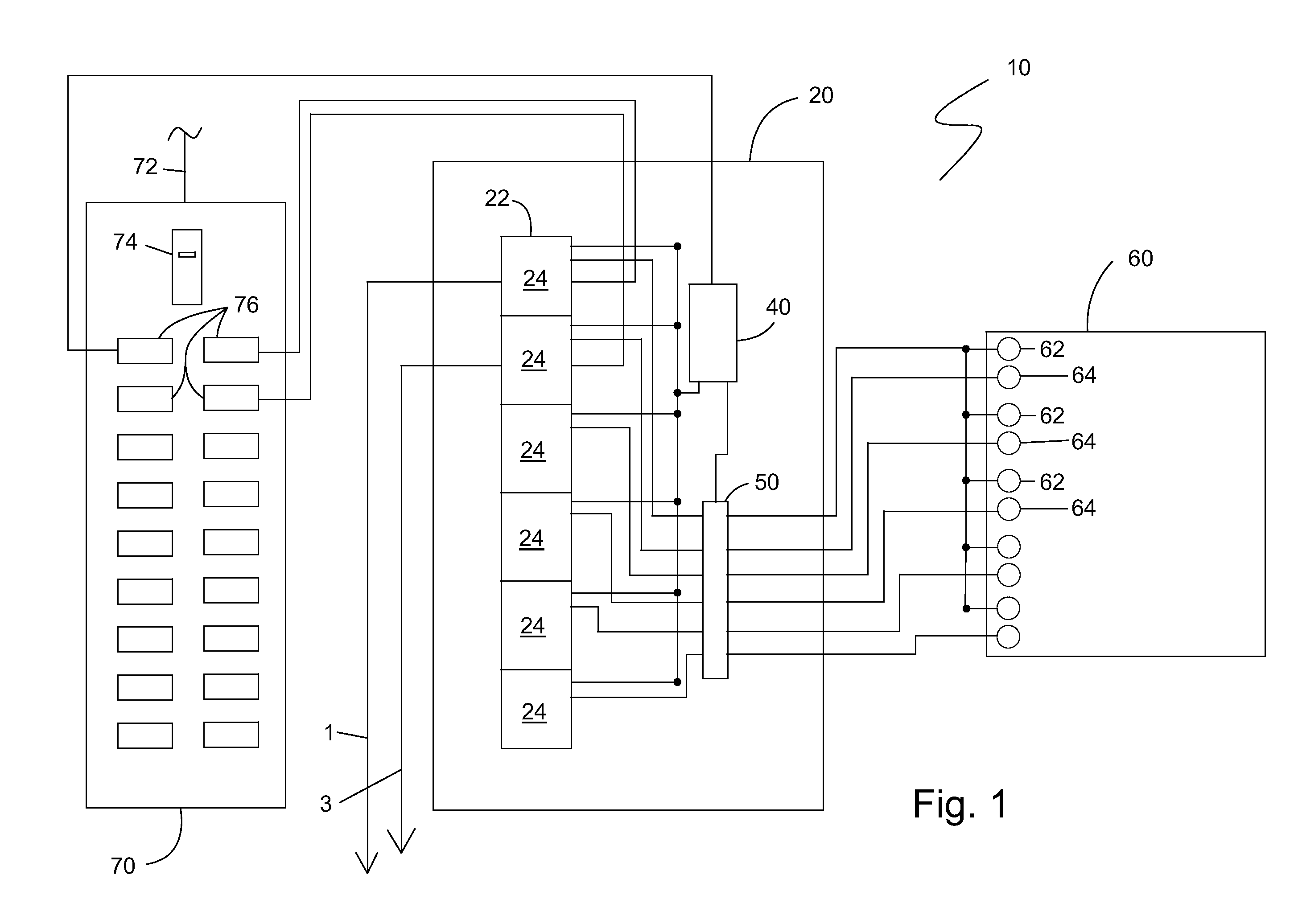
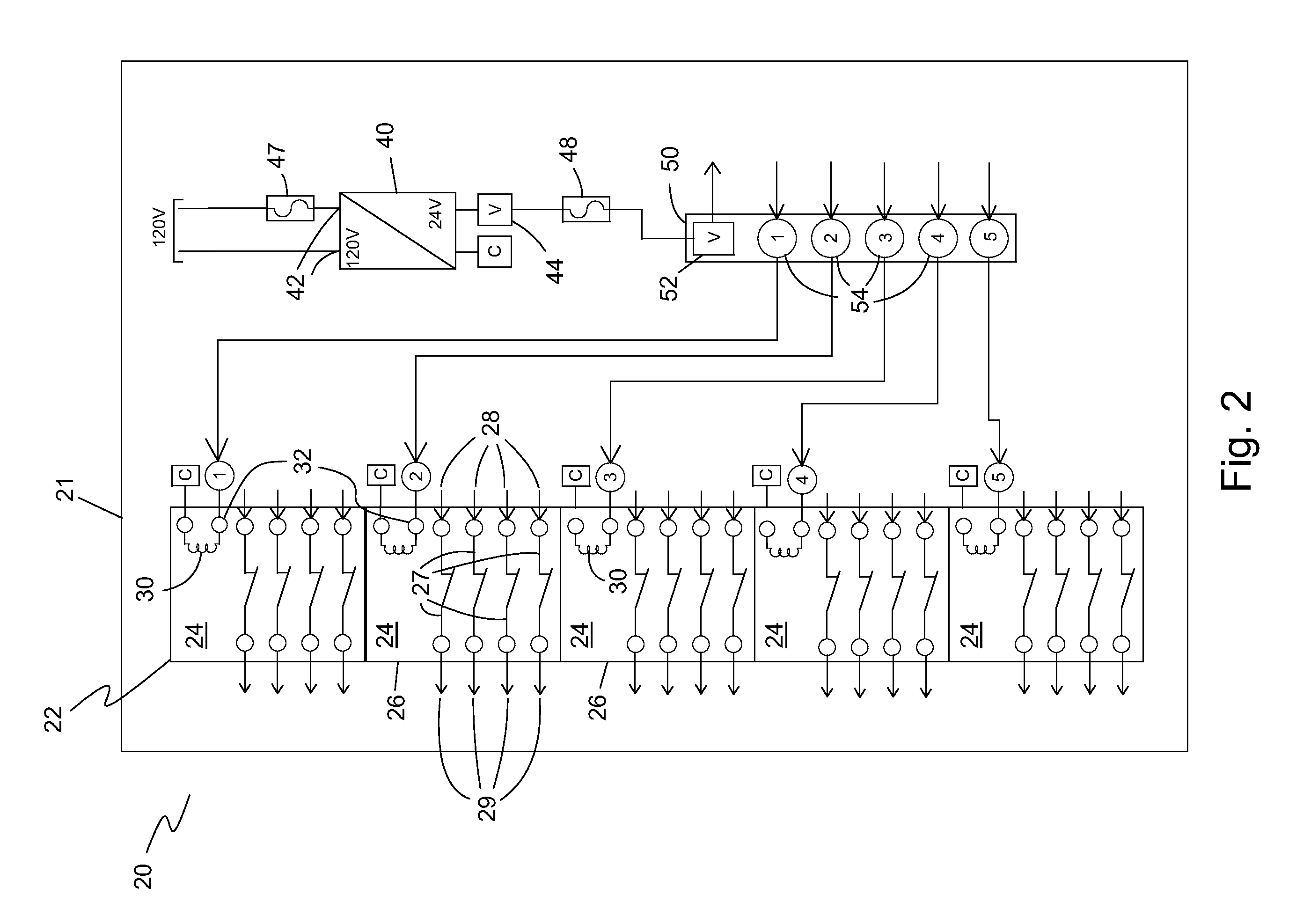
[0028]The preferred embodiment(s) of the present invention is illustrated in FIGS. 1-4. FIG. 1 shows a simplified, schematic diagram of a power control system 10. Power control system 10 includes a power intervening panel 20, a direct digital controller 60 and a main breaker panel 70. Power intervening panel 20 includes a power module array 22, a low voltage power supply 40 and a low-voltage signal power relay module 50. Power module array 22 includes a plurality of power contactor modules 24 that are normally-closed contactors. Low voltage power supply 40 is electrically coupled to power relay module 50 and to low voltage signal relay module 50. The electrical coupling between low voltage power supply 40, power relay module 50 and power module array 22 defines a portion of a low voltage circuit that is used to switch off each of the plurality of power contactor modules 24 of power module array 22.

[0029]Main breaker panel 70 is typically connected to a main power line 72, which may ...


PUM


Abstract

An electrical power management system includes a power intervening panel having a low voltage power supply having a low voltage output electrically coupled to a low voltage circuit, a low voltage common and a power load input, a power module array having a plurality of power contactor modules wherein each of the plurality of power contactor modules has a power contactor with a power load input and a power load output switchable between a closed and an open position and a low voltage switch operably connected to the power contactor for switching the power contactor between the closed and the open position, a low voltage signal relay module having a plurality of signal couplings wherein a primary coupling is a low voltage signal output connected to the low voltage power supply for transmitting a low voltage output signal to one of a direct digital controller and a digital timer and wherein a secondary coupling is a low voltage signal input for receiving the low voltage output signal from one of the direct digital controller and the digital timer, the secondary coupling being electrically coupled to the low voltage switch of one of the plurality of power contactor modules, and an enclosure containing the low voltage power supply, the power module array and the low voltage signal relay module.

Description

BACKGROUND OF THE INVENTION[0001]1. Field of the Invention[0002]The present invention relates generally to electrical power systems. Particularly, the present invention relates to electrical power control systems.[0003]2. Description of the Prior Art[0004]Conventional electrical circuit panel boards such as those used to control lighting circuits include standard electrical-mechanical breakers that control various circuits and / or certain electrical devices attached to those circuits. To energize the circuit, the circuit breaker must be switched on. Circuit breakers found in conventional circuit panel boards are typically not designed for switching purposes. Operating those circuit breakers manually as a means of switch control is not recommended by the manufacturers and certainly not a realistic means of proper energy management.[0005]Building and / or energy management systems have been employed for as long as commercial buildings have existed. The earliest and simplest systems inclu...

Claims


Application Information

Patent Timeline
IPC IPC(8): G06F19/00
CPCH02J3/14Y04S20/246Y02B70/3283H05B37/0254H05B47/18H02J2310/14Y02B70/30Y04S20/222Y02B70/3225
Inventor KIBBIE, JEFFREY
Owner LEO WHITE LLC
Why Eureka
Try Eureka