
Snowshoe with pivoted boot binding

a technology of boots and bindings, applied in the field of pitch, can solve the problems of unpractical adjustment of bias angle, user's objectionable snow-flip effect, and users with a particular gait style tend to generate a considerable snow-flip,

Active Publication Date: 2011-05-19
K 2 CORP
View PDF8 Cites 6 Cited by
  • Summary
  • Abstract
  • Description
  • Claims
  • Application Information

AI Technical Summary

Benefits of technology

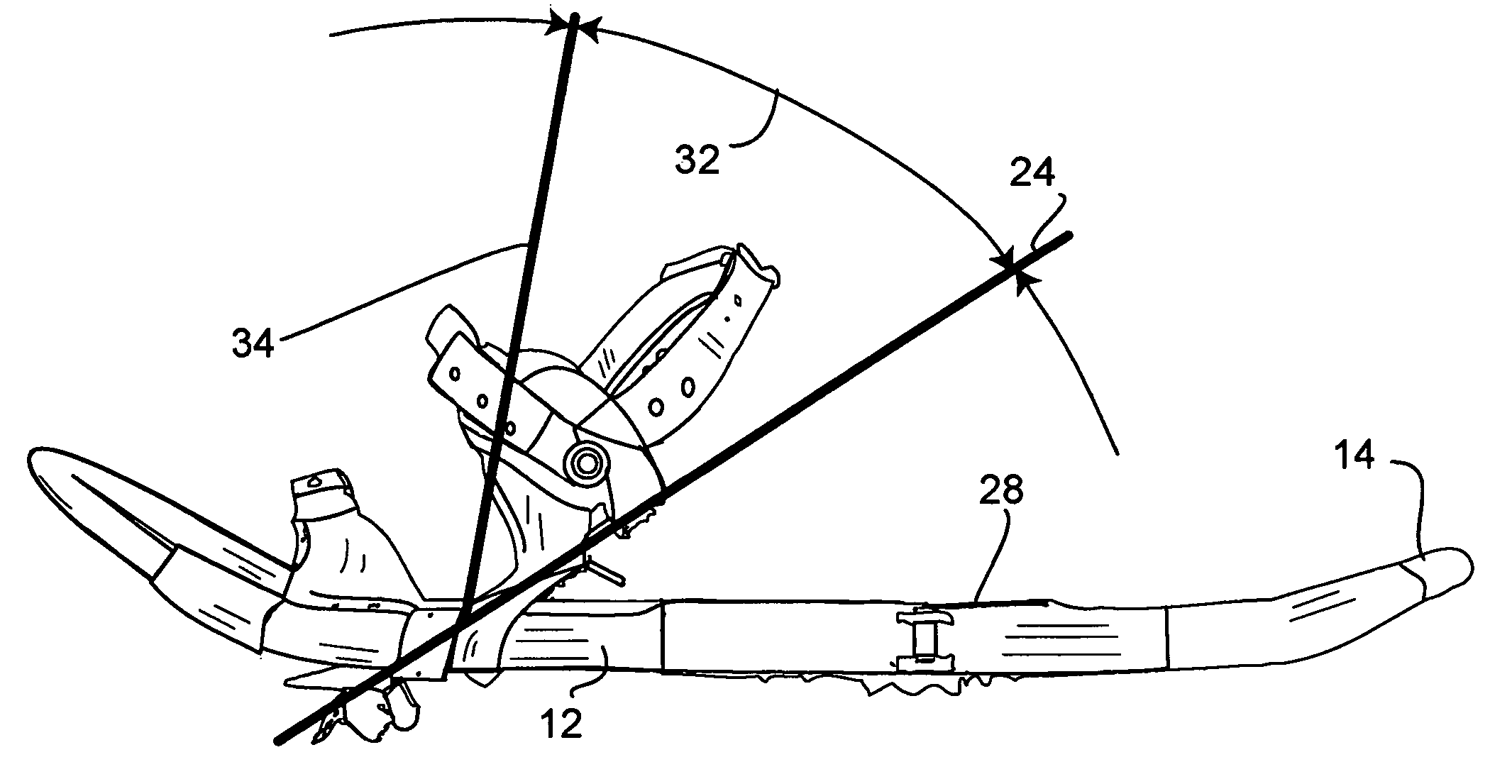
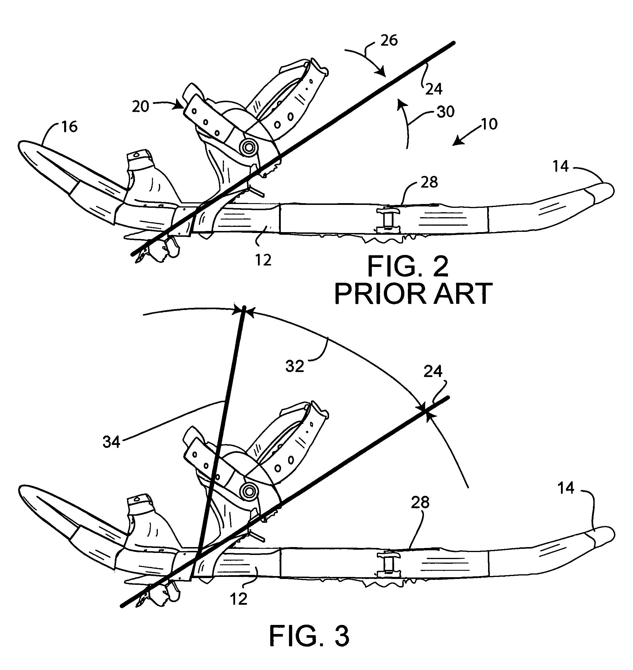
[0007]The invention eliminates the snow-flip problem. The suspension system of the invention is pre-loaded to bias the tail of the snowshoe toward a prescribed angle relative to the binding platform, but to allow free rotation of the snowshoe on the binding when the binding is pitched forward beyond the neutral position. This avoids loading the binding / snowshoe suspension when the binding is at an extreme pitch angle, as the user advances the opposite foot to a forward position. Thus, when the user lifts the rear, deeply pitched foot (“toe-off” position), there is no bias on the snowshoe deck tending to lift and flip up its tail end.
[0010]In one specific embodiment the rotating connection includes a rotation limiter essentially preventing the deep pitch pivot from extending beyond a selected angle (which may be about 60°, 70° or 80°, for example) relative to the snowshoe deck. This can be effected by a rotation limiting tab on the binding platform that engages with structure of the support frame when the arc of rotation reaches the prescribed limit.
[0013]In another embodiment of the invention the neutral position can be at or near 0°, with essentially no tail-down biasing of the snowshoes. Some Tubbs snowshoes and Crescent Moon snowshoes have their bindings suspended by a simple “toe chord”, which permits forward pitch pivoting of the binding on the snowshoe under spring force, but without any tail-down bias. Whether suspended by a toe chord or other spring suspension, this further embodiment of the invention can have a support frame suspended at essentially 0° degrees or deck-parallel position. The support frame is thus biased back toward the parallel position but is allowed to pitch forward against the spring bias. The binding is then attached at a horizontal pivot to the support frame for free-pivoting. In this embodiment the binding includes a locking feature to selectively hold the binding down against the support frame when desired. Thus, the user can select free-pivoting, which will allow the boot to rotate forward freely and without snow-flip, or spring-biased pitch movement with the binding fixed to the suspended support frame, still retaining the benefits of a suspended binding which allows flexibility including some roll of the boot on side terrain.

Problems solved by technology

Although the spring-loaded suspension system of the above patent works very well, some users find the snow-flip effect objectionable.
In particular, some users with a particular style of gait tend to generate a considerable snow-flip.
The adjustment of the bias angle, to the point that the neutral position was at a very high pitch angle, was not practical.
Spring tension adjustment was only partially effective and was not capable of completely eliminating the snow-flip effect.

Method used


Image

  • Snowshoe with pivoted boot binding
  • Snowshoe with pivoted boot binding
  • Snowshoe with pivoted boot binding

Examples


Embodiment Construction

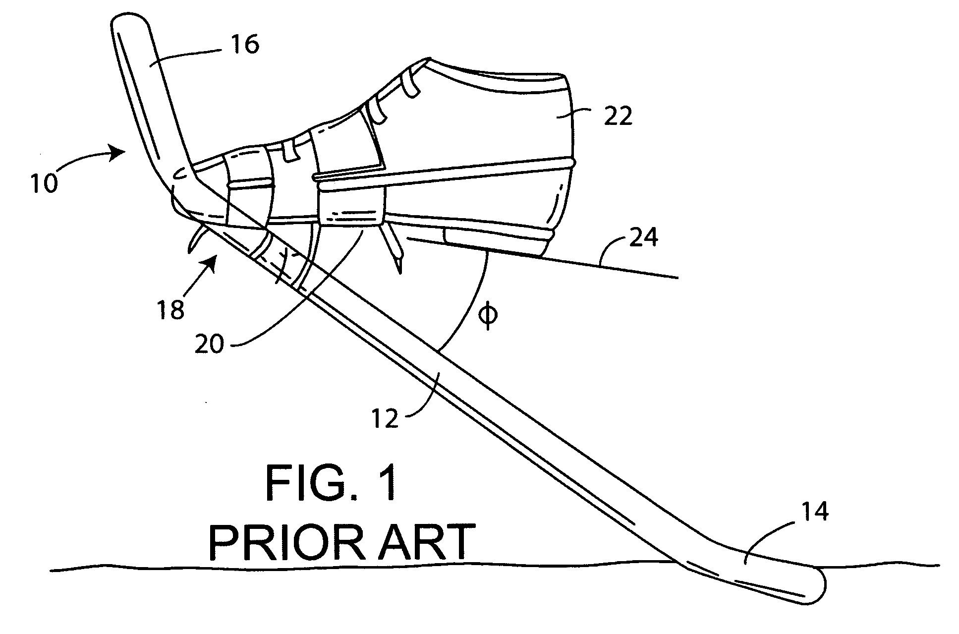
[0022]FIG. 1 shows schematically a snowshoe 10 according to prior art, as in U.S. Pat. No. 5,699,630, with a peripheral frame 12 defining a snowshoe tail 14 and snowshoe nose 16, and with a spring-loaded suspension system generally indicated at 18. The suspension system provides for pivoting of the binding, schematically shown at 20, and the user's boot 22 about a pitch axis, with the binding being spring-biased via the suspension system toward a neutral position as shown in the drawing. The neutral position is at an angle φ. The angle φ in some cases is about 30°-45°. As explained above, this type of suspension exerts a rotational biasing force toward the neutral position, whether the boot is tipped heel-downwardly toward the snowshoe or further pitched forward beyond the neutral position. This is outlined in FIG. 2, also showing the prior art system. The neutral position is shown in FIG. 2 and indicated by the line at 24 in the drawing. The upper arrow 26 indicates an arc of pitch...


PUM


Abstract

A snowshoe of the general type as described in U.S. Pat. No. 5,699,630 has an improved spring-loaded suspension system that reduces or eliminates snow flip as the user lifts the boot and advances it forward. In a principal embodiment the footbed and front claw of the binding are positioned on a spring-suspended frame in such a way that the footbed / claw can freely rotate relative to the snowshoe deck beyond a certain degree of pitch angle.

Description

BACKGROUND OF THE INVENTION[0001]This invention concerns snowshoes with provision for pitch rotation of the snowshoe deck relative to the boot binding, and especially such pitch-rotating snowshoes wherein some form of spring urges the snowshoe deck to rotate toward a defined neutral position relative to the boot and binding.[0002]Atlas Snowshoe Co. U.S. Pat. No. 5,699,630 shows an example of the type of snowshoe to which this invention applies. The tubing frame-type snowshoe has a boot binding that connects to the frame via a tensioned strap. The strap or straps extend from the binding platform left and right to connections with the tubing frame, wrapping around the frame. This allows rotation of the binding in the pitch direction relative to the snowshoe deck, while also exerting a force as the binding is rotated, urging the binding to rotate back toward a neutral position defined by the strap alignment. The spring function in the snowshoe of U.S. Pat. No. 5,699,630 is primarily ac...

Claims


Application Information

Patent Timeline
IPC IPC(8): A43B5/04
CPCA63C13/003A43B5/04A43B5/0401A63C13/006
Inventor BARCHET, CHRIS
Owner K 2 CORP
Learn More