Master tire and method of inspecting tire uniformity tester using the master tire

Active Publication Date: 2011-05-19
KOBE STEEL LTD
View PDF6 Cites 17 Cited by
  • Summary
  • Abstract
  • Description
  • Claims
  • Application Information

AI Technical Summary

Benefits of technology

[0031]With the master tire according to the present invention, the change in the characteristics due to the effects of environmental conditions, such as temperature, or due to the effects of degradat

Problems solved by technology

The force variations generated in the tire are mainly caused by non-uniformity in hardness and thickness of rubber and depending on circularity.
In a general measuring apparatus, the entire performance of the measuring apparatus is checked with reference to a test piece having known values (for example, the prototype kilogram in the case that the general measuring apparatus is a weight measuring apparatus); however, such checking is impossible in the case of this kind of tire uni

Method used


Image

  • Master tire and method of inspecting tire uniformity tester using the master tire
  • Master tire and method of inspecting tire uniformity tester using the master tire
  • Master tire and method of inspecting tire uniformity tester using the master tire

Examples


first embodiment

[0044]First, a tire uniformity tester (hereafter referred to as a tire tester) for carrying out accuracy inspection using a master tire according to this embodiment will be described.

[0045]In the tire tester described below, accuracy inspection is carried out using the master tire according to the first embodiment and a master tire according to a second embodiment.

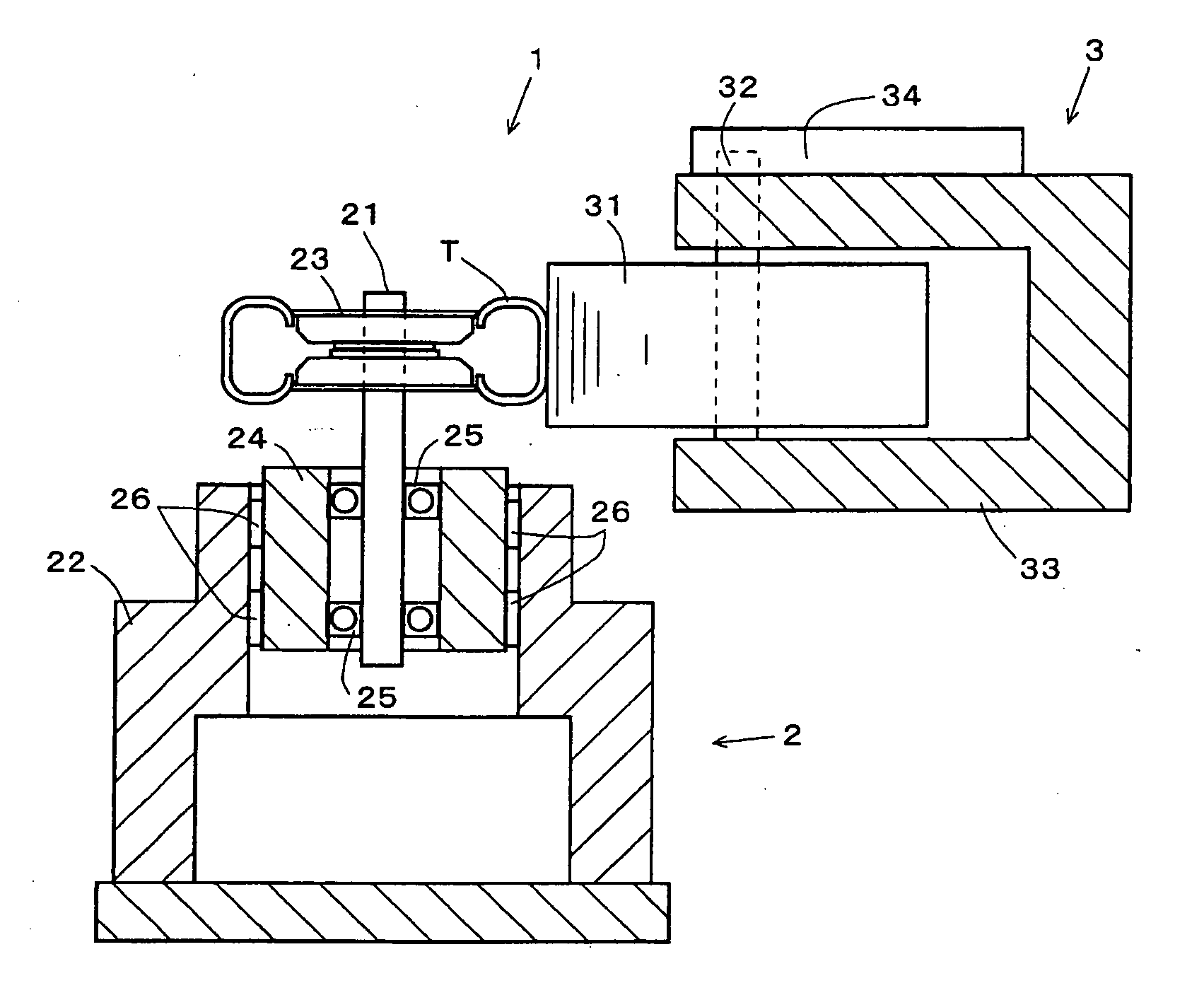
[0046]As shown in FIG. 1, this tire tester 1 is equipped with a tire rolling device 2 on which an actual tire T or a master tire 100 can be mounted and a drum device 3 disposed on the side of the tire rolling device 2.

[0047]The tire rolling device 2 is equipped with a spindle 21 extending in the vertical direction and a support member 22 for rotatably supporting the spindle 21. A rim 23 on which the tire T is mounted can be disposed at the upper end portion of the spindle 21. The tire T can be mounted on the tire rolling device 2 by mounting it on this rim 23. The spindle 21 is accommodated in a bearing housing 24 in a sta...

second embodiment

[0064]Next, a master tire according to a second embodiment will be described.

[0065]In this embodiment, the same components as those according to the above-mentioned embodiment are designated by the same reference characters. Their functions are also the same.

[0066]FIG. 4 is a sectional view showing a master tire 160 according to this embodiment. This master tire 160 is configured so that the cylindrical member 110 is installed so as to be preliminarily inclined at a predetermined angle with respect to the spindle 21. Hence, the cylindrical member 110 tends to return to its horizontal position when pressed by the rotation drum 31 as shown in FIG. 5. At that time, a moment force is generated and a load balanced with the moment is generated in the lateral direction.

[0067]Since the above-mentioned moment changes as the master tire 160 rotates, the load in the lateral direction of the tire changes and appears as the LFV.

[0068]FIG. 6 shows an example in which the master tire 160 according...

third embodiment

[0084]Next, a master tire according to a third embodiment will be described. The master tire according to this embodiment is suited for such a tire tester 51 as shown in FIG. 7.

[0085]As shown in FIG. 7, this tire tester 51 is equipped with a main frame 60 constructed in a gate shape on the floor. The main frame 60 is equipped with an upper shaft 61 being extendable and retractable in the vertical direction by virtue of a lifting mechanism, not shown, and an upper rim 62 removably provided at the lower end of the upper shaft 61. A lower rim 63 for holding the tire T in cooperation with the upper rim 62 is provided below the upper rim 62.

[0086]A spindle 64 is rotatably supported on a spindle housing secured to the main frame 60 so as to be relatively rotatable with respect to the spindle housing 65 by the driving of a motor 66. A rotation drum 70 is provided on the side of the spindle 64 so as to be driven and rotated, and the rotation drum 70 can make contact with the tire T held on ...


PUM


Abstract

The present invention provides a master tire for inspecting the accuracy of a tire tester easily and securely. A master tire 100 according to the present invention is equipped with an upper-lower rim member 120, a cylindrical member 110 equivalent to the tread portion of a tire, and leaf spring 130 secured to the cylindrical member 110 and the rim member 120 with bolts 140 and bolts 142. A spindle 21 is secured to the rim member 120 so that the center axis thereof is not displaced. The rim member 120 is vertical to or slightly inclined with respect to the spindle 21. The cylindrical member 110 is made of a metallic material, such as iron or aluminum, or a hard plastic having stable characteristics.

Description

TECHNICAL FIELD[0001]The present invention relates to a master tire (reference tire) and to a method for inspecting a tire uniformity tester using the master tire.BACKGROUND ART[0002]Conventionally, in the processes of producing ordinary rubber pneumatic tires (hereafter simply referred to as tires), tires having been finally completed through a vulcanization process are subjected to an appearance inspection and a uniformity test, and tires having passed these inspections are shipped. In this kind of uniformity test, for example, a tire to be tested is mounted on the rim body of the mounting rim of a tester, air is filled into the tire at a predetermined pressure from a gas filling portion installed in the rim body, and a characteristic measurement test is carried out.[0003]For example, a tire uniformity tester is used for this characteristic measurement test. In the characteristic measurement test, in a state in which a predetermined load is applied to a tire mounted on a rim so th...

Claims


Application Information

Patent Timeline
IPC IPC(8): G01M17/02
CPCG01M17/022G01M17/02G01M1/16B60C25/002G01L17/005B60Y2304/09
Inventor OKADA, TORUHONKE, KOICHI
Owner KOBE STEEL LTD
Why Eureka
Try Eureka