

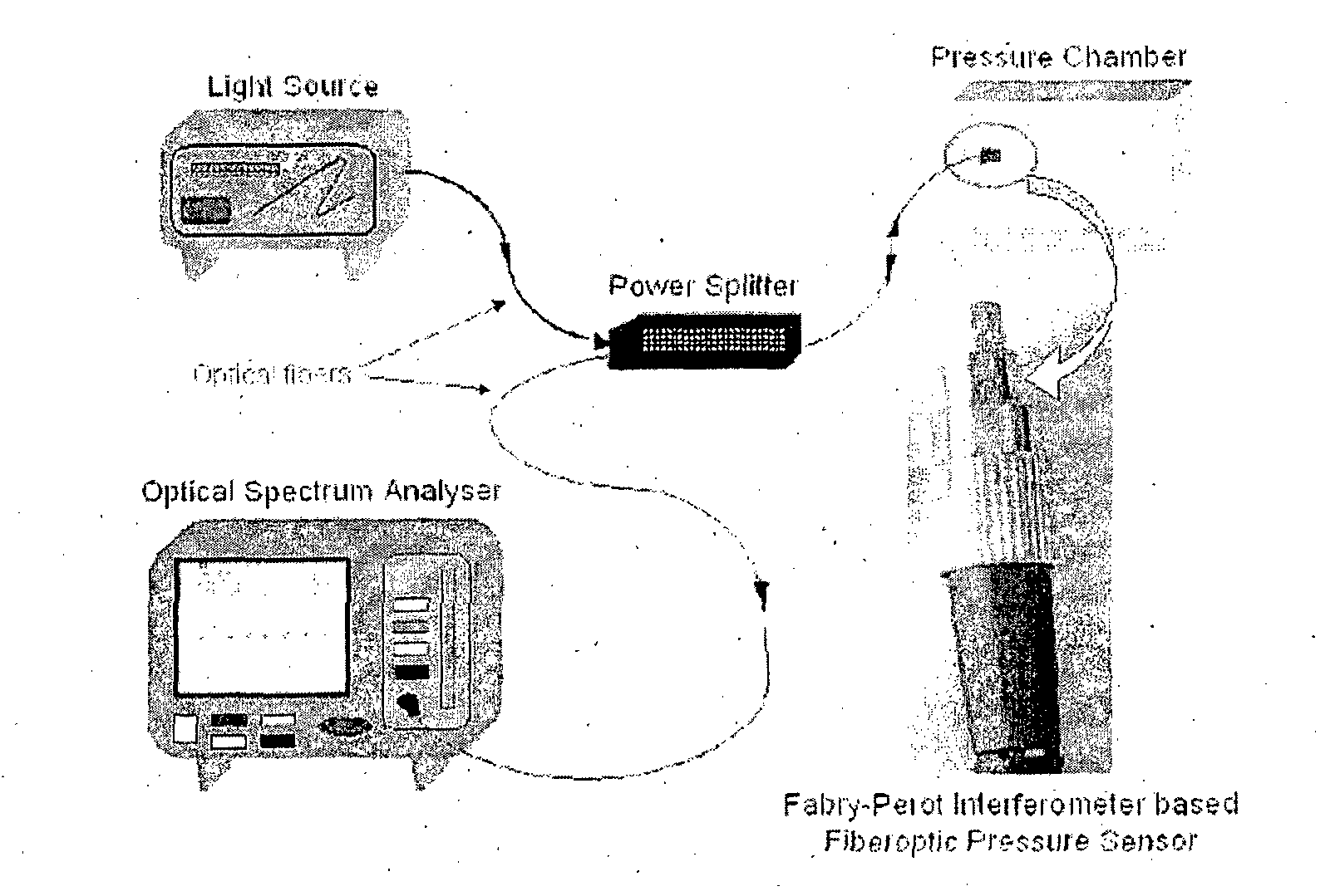
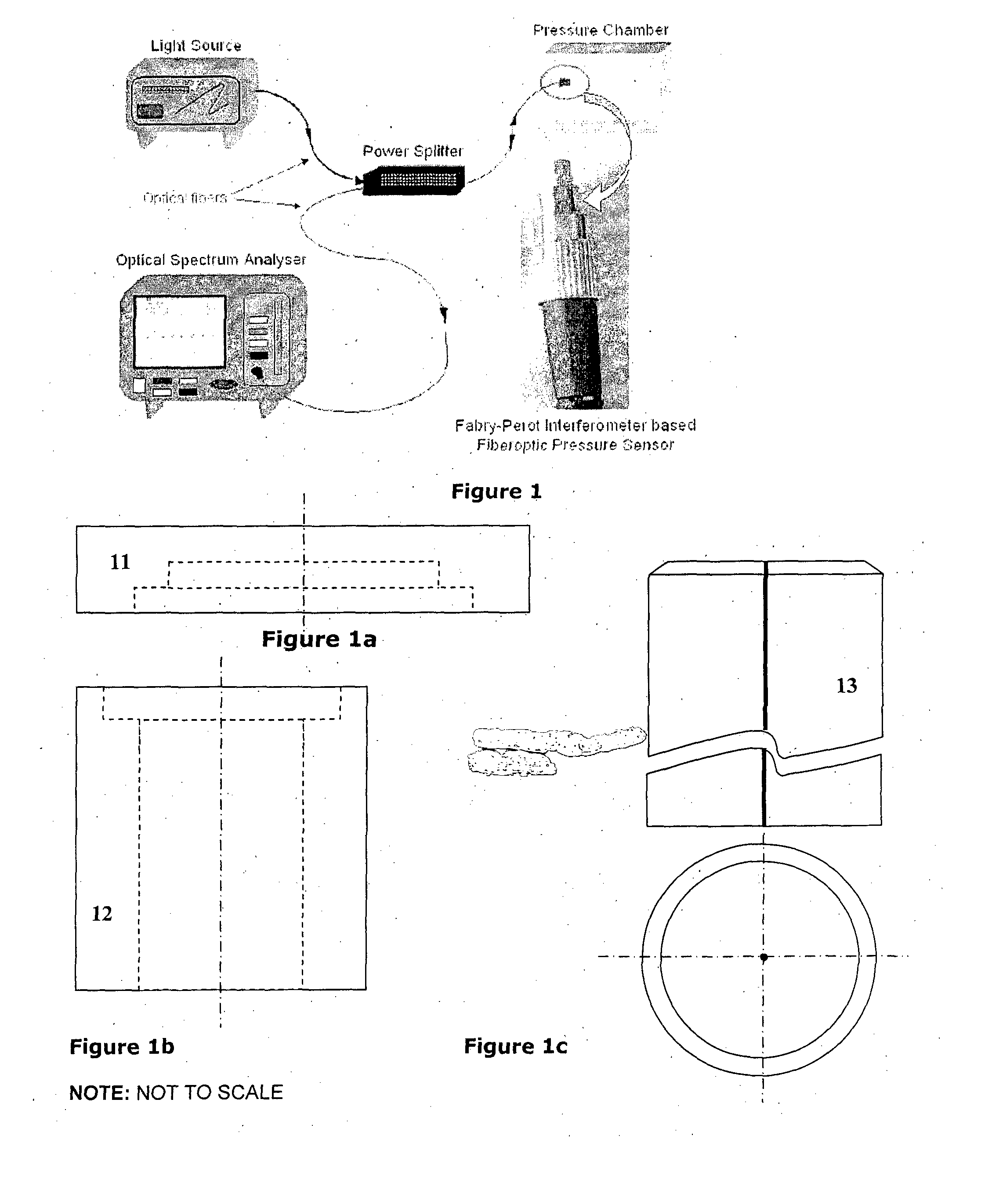
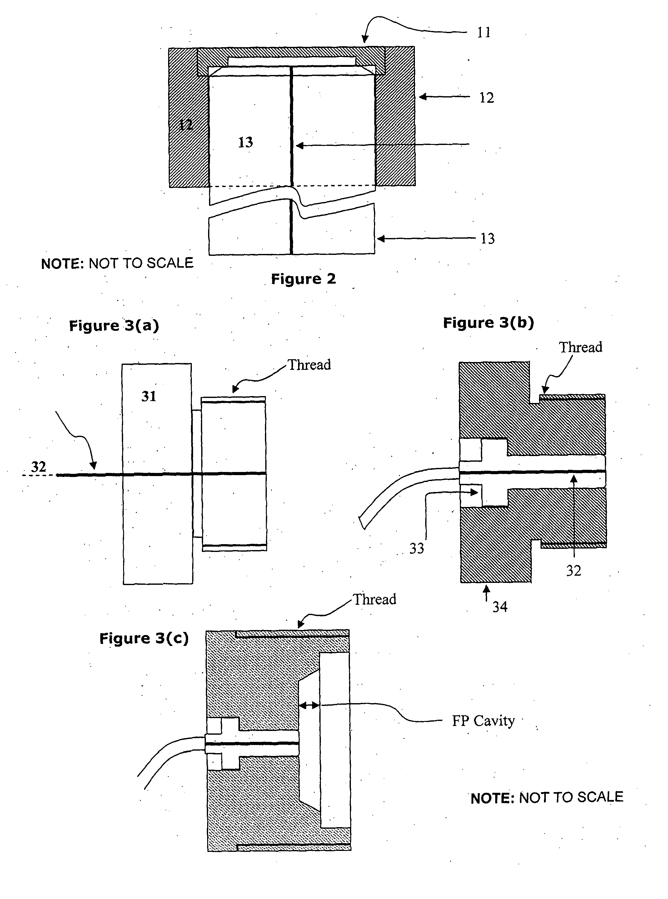
Micromachined metal diaphragm based fabry-perot fiberoptic sensor system and data processing involving the same
a fiberoptic sensor and micro-machined metal technology, applied in the direction of instruments, liquid/fluent solid measurements, heat measurement, etc., can solve the problems of lattice damage, brittleness limitation of conventional semi-conductor materials in the sensor industry,
- Summary
- Abstract
- Description
- Claims
- Application Information
AI Technical Summary
Benefits of technology
Problems solved by technology
Method used
Image

Examples
example
[0202]
λPeak1 / λPeakλPeak1 / λPeak@ 7 bar@ 7 bar@ 1 bar@ 1 barPeak_Order(in nm)(in μm−1)Peak_Order(in nm)(in μm−1)m855.061.169509n857.6041.166039m − 1864.041.157354n − 1866.2851.154355m − 2873.4681.144862n − 2875.4141.142317m − 3883.3461.132059n − 3884.9921.129954m − 4892.8461.120014n − 4894.1221.118416m − 5902.8461.107609n − 5903.71.106562m − 6913.1291.095136n − 6914.3261.093702m − 7923.6291.082686n − 7924.3061.081893m − 8934.1291.070516n − 8934.8061.069741m − 9945.1291.058057n − 9945.3061.057859
[0203]Literature shows that
λm=2∫ / m1 / λm=m / 2∫(slope B=½∫)
[0204]Where l is cavity length & m is the order of peak. It shows that slope for best fit line is ½l; where l is the cavity length. The linear plots above are showing the slope as −ve; while it is positive in above equation. If look carefully in the graph, we will see that x axis is reversed in the graphs, so slope with +ve x axis is +ve.
Cavity length at 1 bar (½B)=41.493 μm; B=0.01205 μm−1
Cavity Length at 7 bar (½B)=40.355 μm; B=0.01239 μ...
PUM
 Abstract
Description
Claims
Application Information