Apparatus and method for providing a controllable supply of fluid to subsea well equipment

a technology of subsea wells and apparatus, which is applied in the direction of fluid couplings, wellbore/well accessories, sealing/packing, etc., can solve the problems of increasing the cost of the system, requiring significant space for iwocs, and requiring significant capital and operational costs

Active Publication Date: 2011-05-19
CHEVROU USA INC
View PDF12 Cites 81 Cited by
  • Summary
  • Abstract
  • Description
  • Claims
  • Application Information

AI Technical Summary

Benefits of technology

[0015]The pumping of the fluid in the pumping device can include receiving the fluid at a high pressure pump and a low pressure pump that are disposed on a skid carried by an ROV. The pumping device, attached to the ROV, can be repeatedly moved to a position proximate the hydraulic power unit on the seabed and fluidly connected to the hydraulic power unit and reservoir subsea to refill the accumulator with the pressurized fluid.
[0016]The pressurized fluid can be stored in multiple accumulators of the hydraulic power unit and at different pressures, e.g., at a first pressure in a first, low pressure accumulator and at a second, higher pressure in a second, high pressure accumulator. Controlling the output of the pressurized fluid from the hydraulic power unit to the subsea equipment can include controlling multiple outputs at multiple different pressures. In each accumulator, the pressurized fluid can be stored in a plurality of bottles, each bottle having an internal space with at least one gas-filled bladder therein. Each bottle can receive the fluid in the internal space outside the bladder so that the bladder is compressed as the bottle receives the fluid and the bladder expands as the fluid is delivered from the bottle.

Problems solved by technology

The workover umbilical and rig required for the IWOCS increase the cost of that system, and the capital and operational costs can be significant, especially for workovers of deep subsea wells.
Further, the IWOCS generally requires significant space on the topside facility.
Such as system typically still requires a significant amount of space on the topside facility, e.g., for providing the umbilical to the subsea equipment for power and / or communication, for equipment associated with the ROV such as a winch and A-frame, and the like.

Method used


Image

  • Apparatus and method for providing a controllable supply of fluid to subsea well equipment
  • Apparatus and method for providing a controllable supply of fluid to subsea well equipment
  • Apparatus and method for providing a controllable supply of fluid to subsea well equipment

Examples


Embodiment Construction

[0025]The present invention now will be described more fully hereinafter with reference to the accompanying drawings, in which some, but not all embodiments of the invention are shown. Indeed, this invention may be embodied in many different forms and should not be construed as limited to the embodiments set forth herein; rather, these embodiments are provided so that this disclosure will satisfy applicable legal requirements. Like numbers refer to like elements throughout.

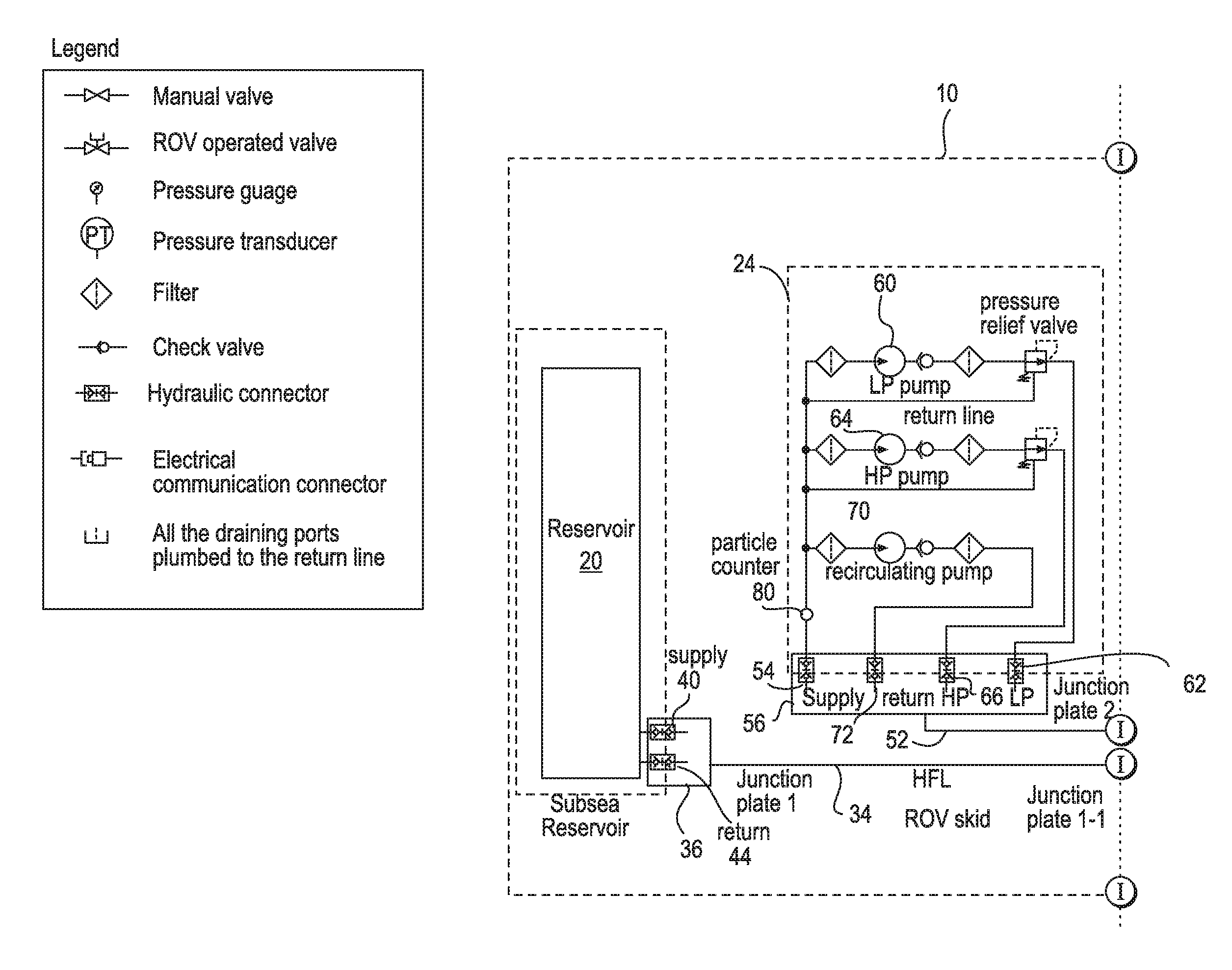
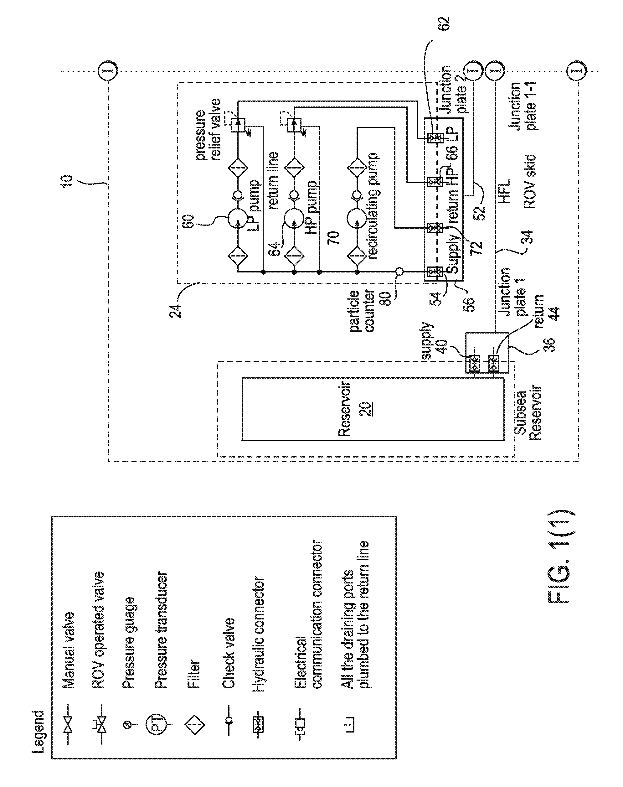
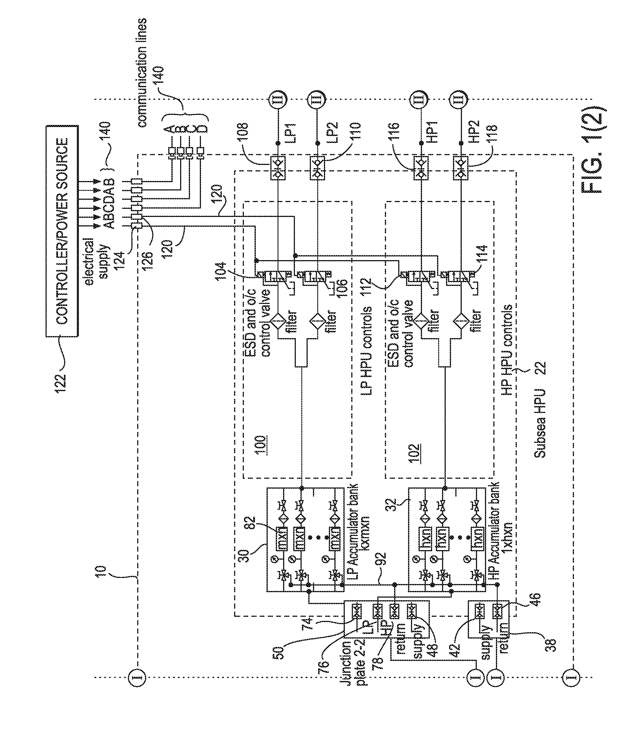
[0026]Referring now to the drawings and, in particular, to FIG. 1, there is shown an apparatus 10 for providing a controllable supply of fluid to subsea equipment 12 (FIGS. 3-7), including a subsea control module (“SCM”) 18 according to one embodiment of the present invention. For example, the apparatus 10 can be connected to a subsea production control system and can provide a supply of hydraulic fluid to the SCM 18, which can control a variety of types of subsea equipment. In particular, the apparatus 10 can pro...


PUM


Abstract

An apparatus and method for providing a controllable supply of fluid, and optionally power and/or communication signals, to a subsea equipment are provided. The fluid may be a water-based fluid, oil-based fluid, or chemicals. The apparatus includes a reservoir disposed on a seabed for storing a supply of fluid for delivery to the subsea well equipment. A subsea pumping device is configured to receive the fluid from the reservoir, pressurize the fluid, and deliver the pressurized fluid to an accumulator of a hydraulic power unit disposed on the seabed. The hydraulic power unit can store the pressurized fluid and control an output of the pressurized fluid to the subsea well equipment, thereby providing a subsea fluid source for the subsea equipment.

Description

BACKGROUND OF THE INVENTION[0001]1. Field of the Invention[0002]This invention relates to the provision of pressurized fluids used in well operations and, more particularly, to an apparatus and method for providing a controllable supply of fluid, and optionally electrical power and / or communication signals, to a subsea well equipment.[0003]2. Description of Related Art[0004]In the production of fluids from a subsea hydrocarbon reservoir, it is often desired to perform a workover operation to improve or verify certain performance of the well and / or the subsea equipment associated with its operation, such as a subsea Christmas tree, i.e., an assembly of valves, spools, and fittings, used for controlling the operations of a subsea well. For example, in a typical workover operation, the operations of the subsea Christmas tree can be controlled without the well's production system in operation to determine if the tree is operating correctly. Such a workover operation can be performed aft...

Claims


Application Information

Patent Timeline
Patent Type & Authority Applications(United States)
IPC IPC(8): E21B43/01F15B1/02
CPCE21B33/0355
Inventor EMECHETA, CHUKWUEMEKA U.O'DONNELL, THOMAS E.OUJANI, OMIDAN, HAILINGTANJU, BAHA T.SIAPPAS, GEORGE
Owner CHEVROU USA INC
Why Eureka
Try Eureka