Ecologically sensitive mud-gas containment system

a mud-gas containment and ecologically sensitive technology, applied in the direction of combustion types, separation processes, borehole/well accessories, etc., can solve the problems of limited or inexistent capture and safe disposal of waste gas, mud residue within the vent line begins to impede, and the hazard of combustion near the well si

Active Publication Date: 2011-05-19
SPM OIL & GAS PC LLC
View PDF45 Cites 35 Cited by
  • Summary
  • Abstract
  • Description
  • Claims
  • Application Information

AI Technical Summary

Benefits of technology

[0006]The present invention provides an ecologically improved system to capture a mud-gas mixture and to safely dispose of waste gas from a wellbore. In one aspect, the present invention is a single skid having a small footprint, carrying all of the components of a mud-gas containment system. Another aspect of the current invention significantly reduces the opportunity for an inadvertent spill of mud. Particularly, the present invention provides a containment and disposal system for any excess mud-gas mixture resulting from a blow out or other emergency. Any released waste gas is burned in a fluidly connected flare stack carried by the mud-gas containment system. The present invention also allows for removal of any buildup of residual mud in the vent line feeding the flare stack. The mud is transferred from the vent line to the overflow catch tank. For the entire system, captured mud-gas mixture is eventually removed for environmentally friendly recovery, recycling, or disposal.

Problems solved by technology

Unfortunately, the gradual out-gassing of waste gas from the mud mixture creates a combustion hazard near the well site.
Capture and safe disposal of the waste gas is limited or non-existent for such situations.
Unfortunately, currently available mud-gas separators frequently pass some mud with the gas through the vent line with the waste gas.
Over time, the mud residue within the vent line begins to impede and eventually block the flow of waste gas to the flare stack.

Method used


Image

  • Ecologically sensitive mud-gas containment system
  • Ecologically sensitive mud-gas containment system
  • Ecologically sensitive mud-gas containment system

Examples


Embodiment Construction

Apparatus—Mud-Gas Containment System

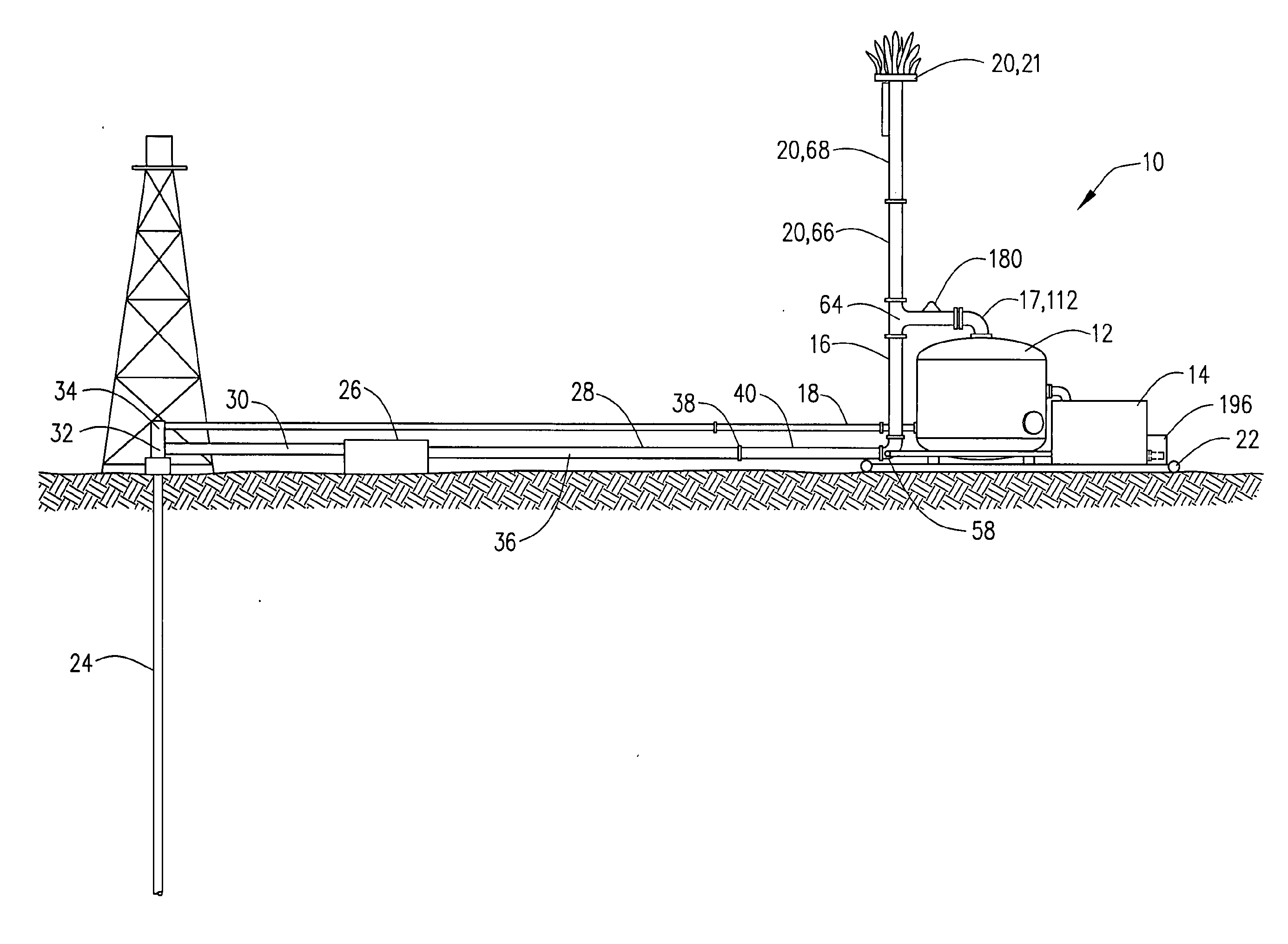
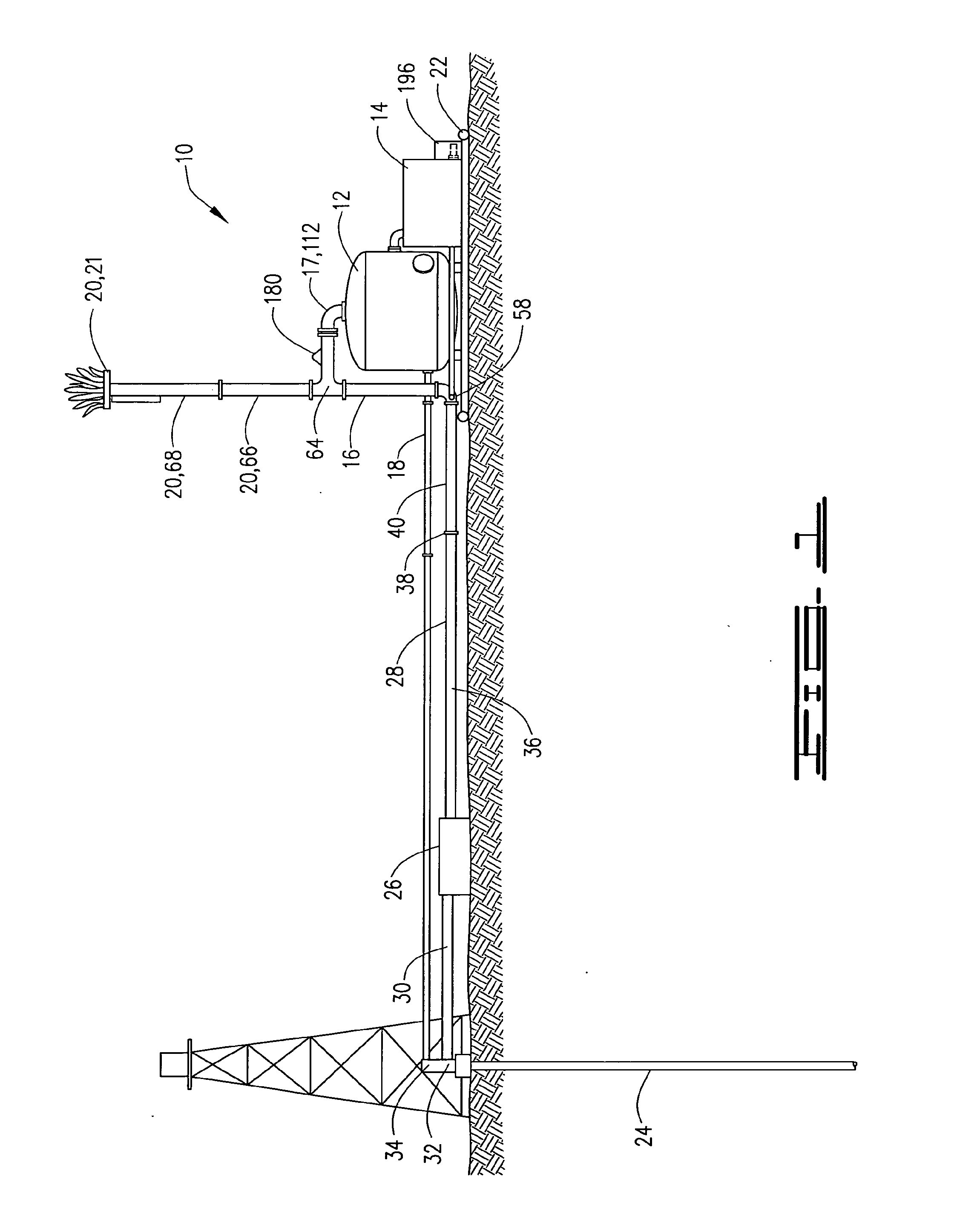
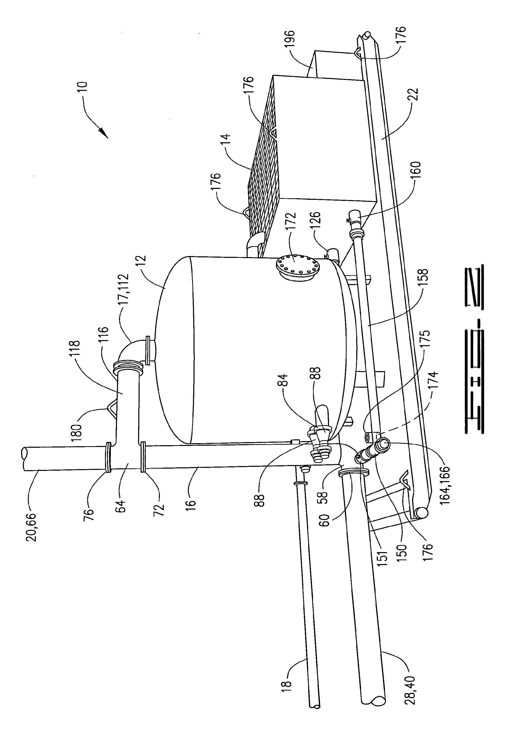
[0025]Referring to FIGS. 1-3, 5A-B, and 12A-B, the entire mud-gas containment system 10 of the present invention is depicted mounted upon skid 22. Skid 22 is designed to be trailered to or from a well site using the United States' state and federal highways without requiring special use permits for width, height or weight.

[0026]The primary, interrelated systems of this invention are vessel 12, catch tank 14, vent line 16, and flare stack 20. Vessel 12 is the first interrelated system, with catch tank 14, vent line 16, and flare stack 20 being the second, third and fourth interrelated systems respectively. The interrelated systems are connected to wellbore 24. Wellbore 24 is connected to vessel 12 and vent line 16 as described herein. As depicted in FIGS. 1-3, 5A-B, and 12A-B, vessel 12, catch tank 14, vent line 16, flare stack 20 and the associated power / control systems are integrally mounted upon and to skid 22.

[0027]Vessel 12 is in fluid communi...


PUM

PropertyMeasurementUnit
angleaaaaaaaaaa
angleaaaaaaaaaa
sizesaaaaaaaaaa

Abstract

This invention relates to an ecologically and environmentally friendly mud-gas containment system. Specifically, this invention relates to a mobile device that is capable of receiving waste gas and, in emergency situations, a volume of a mud-gas mixture from a drilling operation. The waste gas is communicated to a removable flare stack through a vent line. The mud-gas is received at a containment vessel. The impact of the mud-gas within the containment vessel separates the mud-gas into mud and waste gas. The mud is collected for recycling and / or environmentally sensitive disposal. The waste gas from the vessel is communicated to the flare stack. Separate removal ports and conduits are used to remove any residual mud or mud-gas from the vent line and / or containment vessel. Excess mud or mud-gas is communicated to an overflow catch tank for removal. The entire assembly is mounted on a mobile skid sized for highway transportation.

Description

BACKGROUND OF THE INVENTION[0001]This invention relates to a mobile, ecologically and environmentally friendly mud-gas containment system mounted upon a single, highway transportable skid. The mobile device receives, from drilling, production, and / or completion operations, both a waste gas and a volume of drilling mud having entrained and commingled waste gas. The waste gas is communicated to a removable flare stack. The volume of the drilling mud, with entrained waste gas, is received at a containment vessel. This invention also relates to capturing and storing the drilling mud for recycling.[0002]During well drilling, production, and / or completion operations, numerous operational activities and components function simultaneously. Drilling fluid, also called “mud,” is used for the lubrication, cooling, and removal of the cuttings from the well during the drilling, production, and / or completion operations. Because the mud is used within the well, waste gas from the well becomes entr...

Claims


Application Information

Patent Timeline
Patent Type & Authority Applications(United States)
IPC IPC(8): E21B21/06E21B21/01B01D19/00
CPCF23G7/085E21B21/067
Inventor MATHENA, HAROLD DEAN
Owner SPM OIL & GAS PC LLC
Why Eureka
Try Eureka