
Electric Motor

Active Publication Date: 2011-05-19
SEW-EURODRIVE GMBH & CO KG
View PDF6 Cites 15 Cited by
  • Summary
  • Abstract
  • Description
  • Claims
  • Application Information

AI Technical Summary

Benefits of technology

[0003]Example embodiments of the present invention simplify the production of an electric motor and improve the production quality during the manufacture.
[0005]In this context it is advantageous that the end cap provides protection of the core stack. Furthermore, the coherence of the core stack is improved. In addition, the shape of the end cap defines and guides the winding as precisely as possible during its production. Thus, spatial path deviations of the winding tool such as pin winders are able to be compensated, thereby always producing the same winding; in other words, the reproducibility of a desired winding is improved, in particular, and / or the winding speed is able to be increased since greater path deviations are acceptable. A number of shaping features of the end cap contribute to the definition and guidance. First of all, the dome restricts the overall space region of the winding. In addition, the rerouting takes place in a defined area at the base of the dome. Moreover, the grooves ensure that no radial sliding has to be taken into account. The groove distance is so small the same winding is always produced given proper path guidance. But even at greater path speeds of the winding tool and thus greater path deviations, a substantially identical winding is able to be produced in that, despite the fact that the first winding of the coil slides by the distance of one groove in the radial direction, the winding then has an identical form again. Since the distance of the grooves is considerably smaller than the diameter of the winding wire, even the position of the winding wire that has shifted by the distance of one groove leads to a substantially identical winding.
[0006]Furthermore, it is advantageous that there are shaping features at the end cap which make it possible to hold the individual segments together and to align them with the aid of a retaining element.
[0017]In example embodiments, the end cap has a retention offset, which is provided for the form-locking connection with a tool of the winding machine, especially during the production of the winding. It is advantageous that sliding of the end cap caused by forces that arise during the winding is able to be prevented.
[0019]In example embodiments, the winding machine is a type of pin winder. This offers the advantage that complex path courses are able to be completed rapidly during the winding operation.
[0020]In example embodiments, the connecting bar has reinforcement ribs extending in the axial direction and / or in the radial direction, in particular bars that project in the circumferential direction. This advantageously improves the torsional rigidity.

Problems solved by technology

First of all, the dome restricts the overall space region of the winding.

Method used


Image

  • Electric Motor
  • Electric Motor
  • Electric Motor

Examples


Embodiment Construction

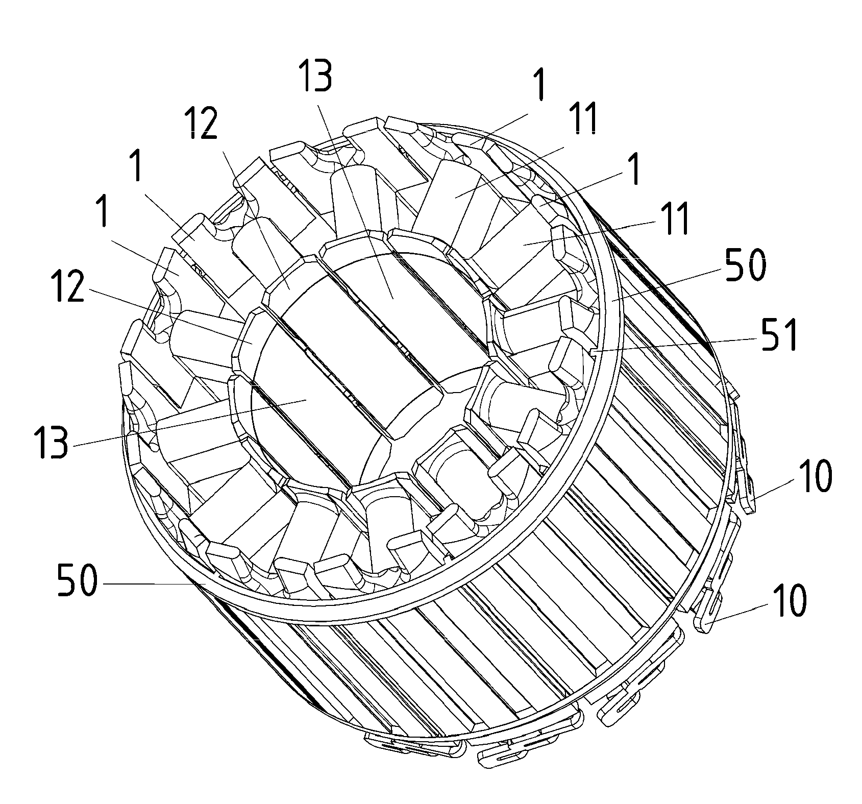
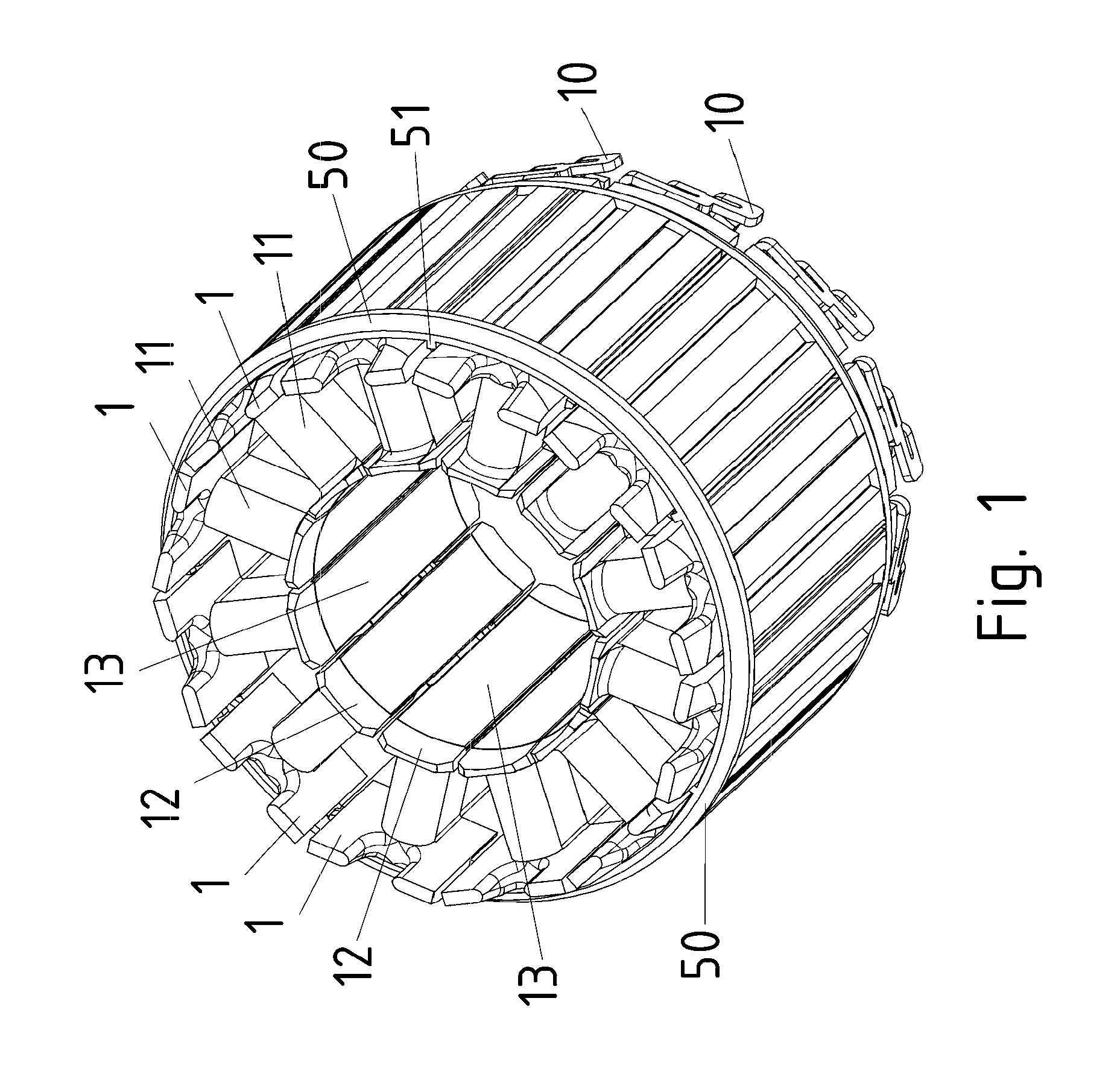
[0045]As shown in FIG. 1, the stator of the electric motor according to an example embodiment of the present invention is made up of individual segments that are disposed one after the other in the circumferential direction. A retaining ring 50, whose snap-in connection regions 51 keep an individual segment connected with form-fitting, is slipped over the stator, so that the cylindrical form of the stator, i.e., the circular alignment of the individual segments, is achieved.

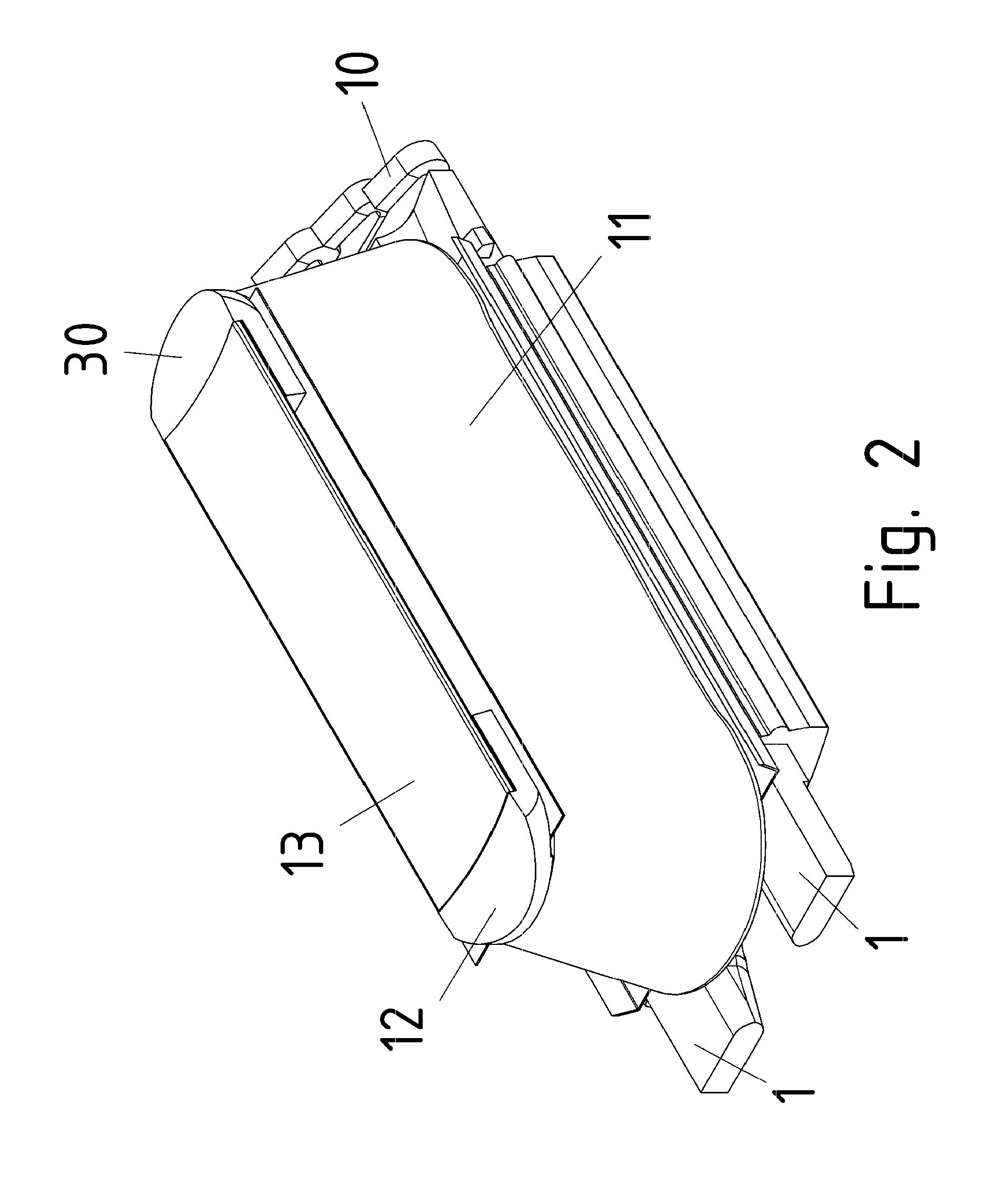
[0046]Each individual segment includes a core stack 13, over which a plastic end cap (12, 30) is slipped at both axial terminal regions. The first end cap is provided axially on the motor output side, and the second end cap is provided axially on the opposite side. The winding of each individual segment is performed automatically, for which purpose a pin winder may be employed.

[0047]The end cap (12, 30) is preferably implemented in mirror-symmetry, the mirror plane including the axis of the motor.

[0048]The end ca...


PUM


Abstract

An electric motor includes a stator made up of individual segments disposed in the circumferential direction, each individual segment including a core stack around which a winding is provided and at whose axial terminal regions end caps are provided, the winding being produced by a winding wire, an end cap including at least one dome, in particular for delimiting the region of the winding, a wire inlet duct for rerouting the winding wire being provided in the base region of the dome, grooves being provided on the end cap, the distance of one groove with respect to the radially following groove and the diameter of the curvature of the respective groove being smaller than the diameter of the winding wire.

Description

FIELD OF THE INVENTION[0001]The present invention relates to an electric motor.BACKGROUND INFORMATION[0002]Electric motors, whose stator includes a core stack, are generally known. Such a core stack is preferably stamp-packed.SUMMARY[0003]Example embodiments of the present invention simplify the production of an electric motor and improve the production quality during the manufacture.[0004]Among features of example embodiments of the present invention in the electric motor are that the electric motor includes a stator which is composed of individual segments disposed in the circumferential direction, each individual segment including a core stack around which a winding is provided and at whose axial terminal regions end caps are situated, the winding being produced by a winding wire, an end cap including at least one dome, in particular for delimiting the region of the winding, and a wire inlet duct for rerouting the winding wire being provided in the base region of the dome, groove...

Claims


Application Information

Patent Timeline
IPC IPC(8): H02K11/00
CPCH02K1/148H02K2203/12H02K15/022H02K3/522
Inventor STARK, TOBIASHETTEL, DOMENIK
Owner SEW-EURODRIVE GMBH & CO KG
Learn More