Infrared vision with liquid crystal display device

US20110115747A1Inactive Publication Date: 2011-05-19MICROSOFT TECH LICENSING LLC

Image

  • Infrared vision with liquid crystal display device
  • Infrared vision with liquid crystal display device
  • Infrared vision with liquid crystal display device

Examples


Embodiment Construction

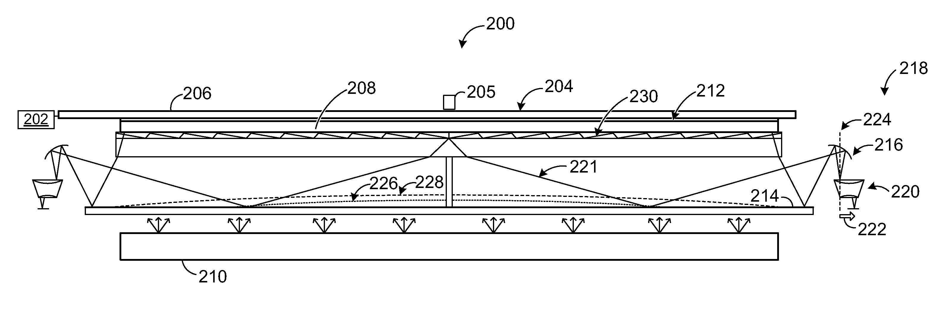
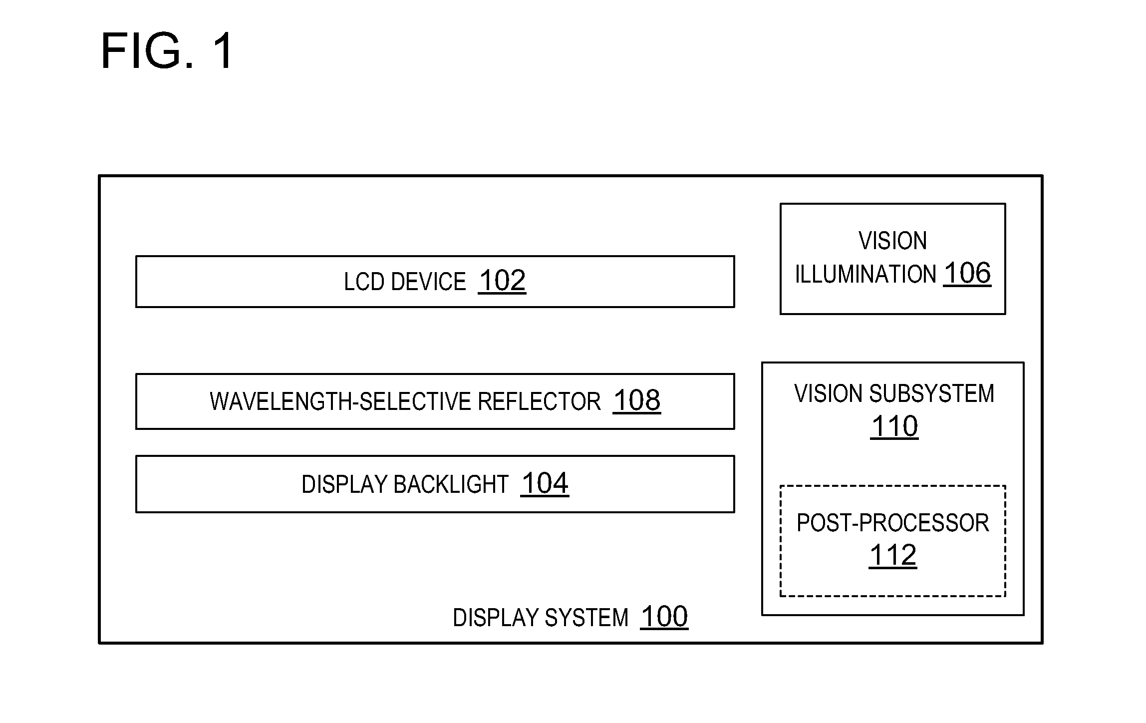
[0013]A display system may utilize LCD-based technologies for visually displaying content such as text, images, photos, movies and the like. As described above, certain design challenges can arise when combining an LCD-based display system with a vision subsystem that is used for optical touch detection or to otherwise optically detect objects on or near the LCD device. The present disclosure provides for a display system employing an LCD device and a smooth wavelength-selective reflector positioned between the LCD device and a display backlight. The wavelength-selective reflector and various other components are arranged to enable an infrared vision subsystem to “see” (detect), or image, objects on or near the outside of the LCD panel without interfering with the illumination of the LCD by the display backlight. Various embodiments of such a system are described in more detail as follows.

[0014]FIG. 1 shows a block diagram of an embodiment of an example display system 100. Such a di...


PUM


Abstract

Various embodiments related to infrared vision for a liquid crystal display (LCD) device are disclosed herein. For example, one disclosed embodiment provides a display system, comprising an LCD device and a display backlight configured to illuminate the LCD device by directing visible light toward an interior surface of the LCD device. The display system further comprises a wavelength-selective reflector disposed between the display backlight and the LCD device and having a smooth surface facing the interior surface of the LCD device, where the wavelength-selective reflector has a wavelength-selective coating configured to cause incident visible light from the display backlight to be transmitted through the wavelength-selective reflector to the LCD device, and cause incident infrared light reflected from an object on or near an exterior surface of the LCD device to be reflected off of the wavelength-selective reflector and directed to an infrared vision subsystem.

Description

BACKGROUND[0001]Display devices may utilize various technologies for displaying images, such as cathode ray tube (CRT) technologies, projection-based technologies, liquid crystal display (LCD)-based technologies, etc. Some display devices may also be configured to detect touches of physical objects on a surface of the display, using technologies such as capacitive detection, resistive detection, optical detection, etc. In some cases, optical detection technologies may be further configured to detect “near-touches” of physical objects located near a surface of the display.[0002]A computing system which combines the functionality of a display device and optical detection such as an infrared vision subsystem may have one or more features compromised as a result of integrating the two technologies. As an example, such a display system may combine a projection-based display system with a standard infrared vision subsystem, however, use of the projection-based display may significantly in...

Claims


Application Information

Patent Timeline
19 May 2011
Publication
US20110115747A1
IPC
G06F3/042; G02F1/1335
CPC
G06F3/042; G06F3/0425
Inventors
POWELL, KARLTON; LIU, ZHIQIANG