Thermal plate with optional cooling loop in electronic display

a technology of electronic display and thermal plate, which is applied in the direction of lighting and heating apparatus, electrical apparatus casings/cabinets/drawers, instruments, etc., can solve the problems of increasing the temperature of the display dramatically, damage to the electrical assemblies, and thermal regulation problems

Active Publication Date: 2011-05-19
MFG RESOURCES INT INC
View PDF39 Cites 94 Cited by
  • Summary
  • Abstract
  • Description
  • Claims
  • Application Information

AI Technical Summary

Problems solved by technology

When used outdoors, high ambient temperatures and solar loading can present several thermal-regulatory issues.
When a display is exposed to direct sunlight this can increase the temperature of the display dramatically due to the solar loading of the front display surface due to the radiative heat of the sun.
This heat must be removed from the display or it may damage the electrical assemblies.
If an LCD is used, high internal temperatures can cause the liquid crystal material to malfunction and may produce noticeable failures on the image.
LEDs can degrade in performance and efficiency when exposed to high temperatures.

Method used


Image

  • Thermal plate with optional cooling loop in electronic display
  • Thermal plate with optional cooling loop in electronic display
  • Thermal plate with optional cooling loop in electronic display

Examples


Embodiment Construction

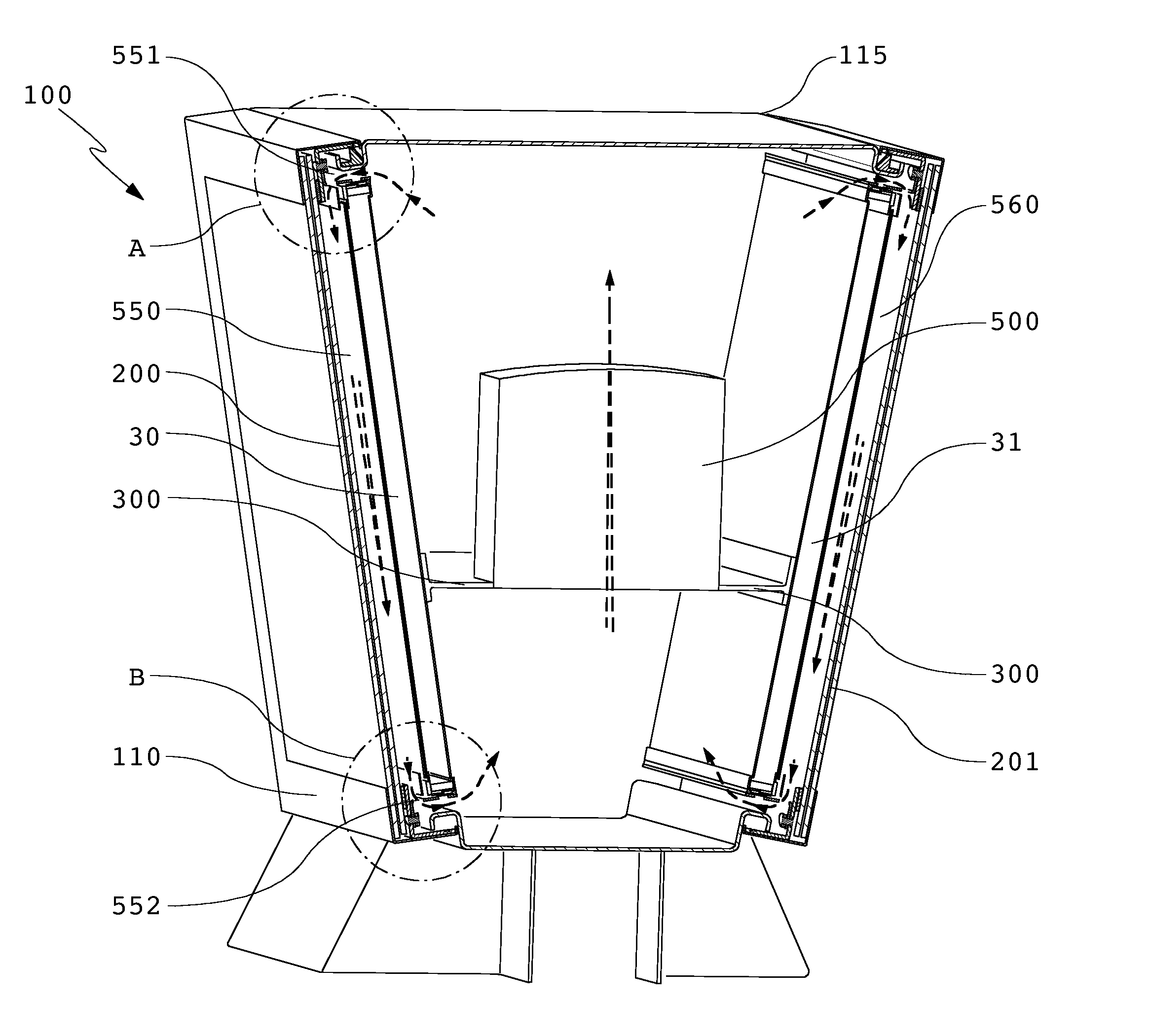
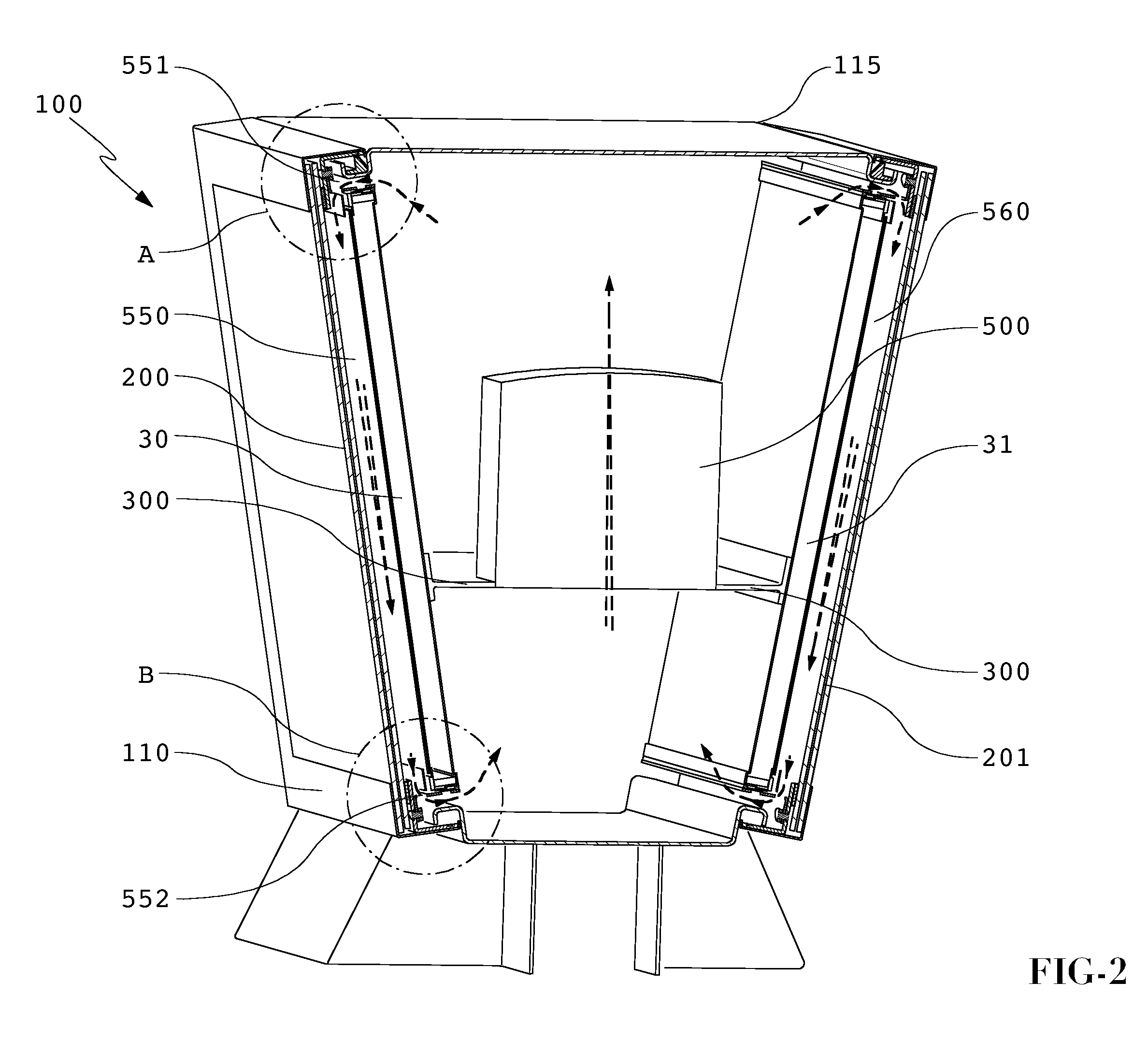
[0006]An exemplary embodiment may contain a thermal plate which can transfer heat from the image assembly to the housing of the display and into the ambient air through convection. A transparent plate assembly may be used which can provide the front surface for a narrow channel of cooling air which may be directed between the transparent plate assembly and the image assembly. The cooling air can also pass over the thermal plate in order to aid in cooling the thermal plate. In some embodiments, the thermal plate may run the entire length of the image assembly and may contain several apertures which allow cooling air to pass through the plate. When using an LCD display with an LED backlight, the heat generated by the LED backlight can also be transferred through the thermal plate and into the display housing as well as the cooling air. The display housing can be sealed and does not require an inlet of ambient air so that the display can be used in environments which have contaminates ...


PUM

PropertyMeasurementUnit
transparentaaaaaaaaaa
forcesaaaaaaaaaa
thermally-conductiveaaaaaaaaaa

Abstract

An electronic display having one or more thermal plates in thermal communication with an image assembly and a thermally-conductive housing (and optional door frame). In some embodiments, the thermal plate is in thermal communication with the door frame which is in thermal communication with the housing. A channel may be defined between a transparent plate assembly and the image assembly where a fan may force cooling air through the channel. The cooling air may also pass through apertures in the thermal plate(s). An exemplary image assembly may provide an LED edge-lit LCD or an OLED display. In some embodiments, two displays may be provided in a back-to-back orientation within a single housing. The display may dissipate heat without the need to ingest ambient air.

Description

CROSS-REFERENCE TO RELATED APPLICATIONS[0001]This application is a non-provisional application and is a continuation in part of U.S. application Ser. No. 12 / 618,104 filed Nov. 13, 2009, which is hereby incorporated by reference as if fully recited herein.FIELD OF THE INVENTIVE CONCEPT[0002]The exemplary embodiments herein are directed towards an electronic display having a thermal plate with an optional cooling loop for conductive and convective cooling.BACKGROUND OF THE INVENTIVE FIELD[0003]Electronic displays are now being used for not only indoor entertainment purposes, but are now being utilized for indoor and outdoor advertising / informational purposes. For example, liquid crystal displays (LCDs), plasma displays, light emitting diode (LED), electroluminescence, light-emitting polymers, organic light emitting diode displays (OLEDs) and many other displays can now be used to display information and advertising materials to consumers in locations outside of their own home or withi...

Claims


Application Information

Patent Timeline
Patent Type & Authority Applications(United States)
IPC IPC(8): H05K7/20H05K7/00F21V29/00G02F1/1333
CPCG02F1/133382G02F1/133385H05K7/20154H05K7/20963F28F3/00G02F2201/36G02F1/133342G02F1/133615H05K7/20972
Inventor DUNN, WILLIAMLE, DONBEDELL, WARE
Owner MFG RESOURCES INT INC
Why Eureka
Try Eureka