Eureka AIR delivers breakthrough ideas for toughest innovation challenges, trusted by R&D personnel around the world.

Liquid crystal display device

a liquid crystal display and display device technology, applied in the field of large-scale liquid crystal display devices, can solve the problems of poor thermal conductivity of the transparent non-reflective plate covering the surface of the liquid crystal panel, affecting the provision of uniform image quality, and affecting the quality of image, etc., to achieve tight closing

Inactive Publication Date: 2011-05-19
NEC CORP
View PDF12 Cites 21 Cited by
  • Summary
  • Abstract
  • Description
  • Claims
  • Application Information

AI Technical Summary

Benefits of technology

[0015]It is an object of the present invention to provide a liquid crystal display device that can implement uniform image quality and high reliability as a liquid crystal display device as well as implement reductions in weight and cost through the use of a simple cooling mechanism. Furthermore, while achieving this object, it is an object to provide a liquid crystal display device that can prevent dust and dirt in the outside air from penetrating LCD panels, that can prevent water droplets caused by rain or the like from coming into contact with the LCD panels and that can prevent the LCD panels from damage caused by external impacts.
[0017]According to the present invention, at least both the tight closing property and cooling performance for the surface of the liquid crystal panel can be satisfied.

Problems solved by technology

At this time, a build up of heat occurs in the air layer because the thermal conductivity of the air layer (the coefficient of thermal conductivity is 0.026 W / mk) is not excellent and the thermal conductivity of the transparent non-reflective plate covering the surface of the liquid crystal panel is not excellent as well.
Consequently, temperature rises or temperature variations occur in the liquid crystal panel, which hamper the provision of uniform image quality, high reliability, and longer lifetime.
In addition, because image quality is also reduced in the configuration that lower the luminance, a problem of market appeal arises in accurately displaying and conveying urgent traffic guides, for example.
Accordingly, it is not said that the above-mentioned methods are not adequate for liquid crystal display devices having dust-proof properties, which are installed in semi-outdoor public facilities such as stations.
This increases the volume and weight of the lamp accommodating unit.
Further, because the fabrication method thereof becomes complicated, costs are increased.
Accordingly, this configuration is a disadvantageous for meeting the recent demands for liquid crystal display devices.
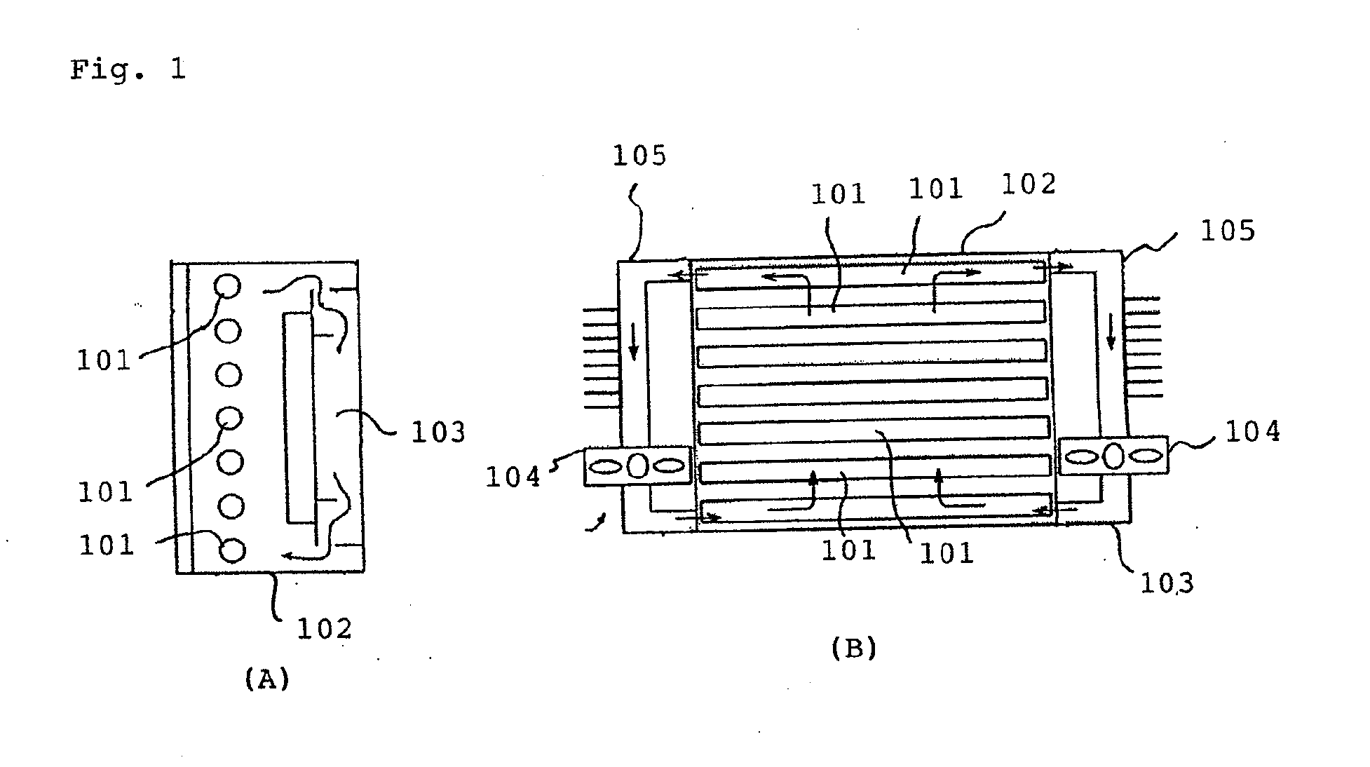
Thus, there is a problem in which the cooling means alone for the fluorescent lamp unit disclosed in the Patent Document 1 is not sufficient to meet the cooling capability and high reliability requirements for satisfying the temperature specifications of all the electronic components that have been mounted, from the viewpoint of the overall liquid crystal display device.
Further, for improving this cooling capability, there is also a problem in that a tight closing property, which is enough to prevent the penetration of dust and dirt flying in the outside air or water droplets, has to be maintained.

Method used


Image

  • Liquid crystal display device
  • Liquid crystal display device
  • Liquid crystal display device

Examples


second embodiment

[0130]A second embodiment of the present invention will be described with reference to FIG. 10. In addition, FIG. 10 shows enlarged area B shown in FIG. 8.

[0131]The configuration of this embodiment is almost the same as the above-mentioned configuration in FIG. 8. However, only one large difference is in that the side surface of fluorescent lamp socket 25a does not come into with the side surface of chassis box 11. More specifically, there is an air layer between the side surface of fluorescent lamp socket 25a and the side surface of chassis box 11.

[0132]In this configuration, in FIG. 10, heat dissipation paths for fluorescent lamp 19 as a heat source, and for inverter circuit board 26a as a heat source, are expressed by a thermal network.

[0133]First, the heat generated from a plurality of fluorescent lamps 19 including other fluorescent lamps 19, not shown, is dissipated into the air around device 1 from three heat dissipation paths 1) to 3) below.

1) A heat dissipation path to the ...


PUM


Abstract

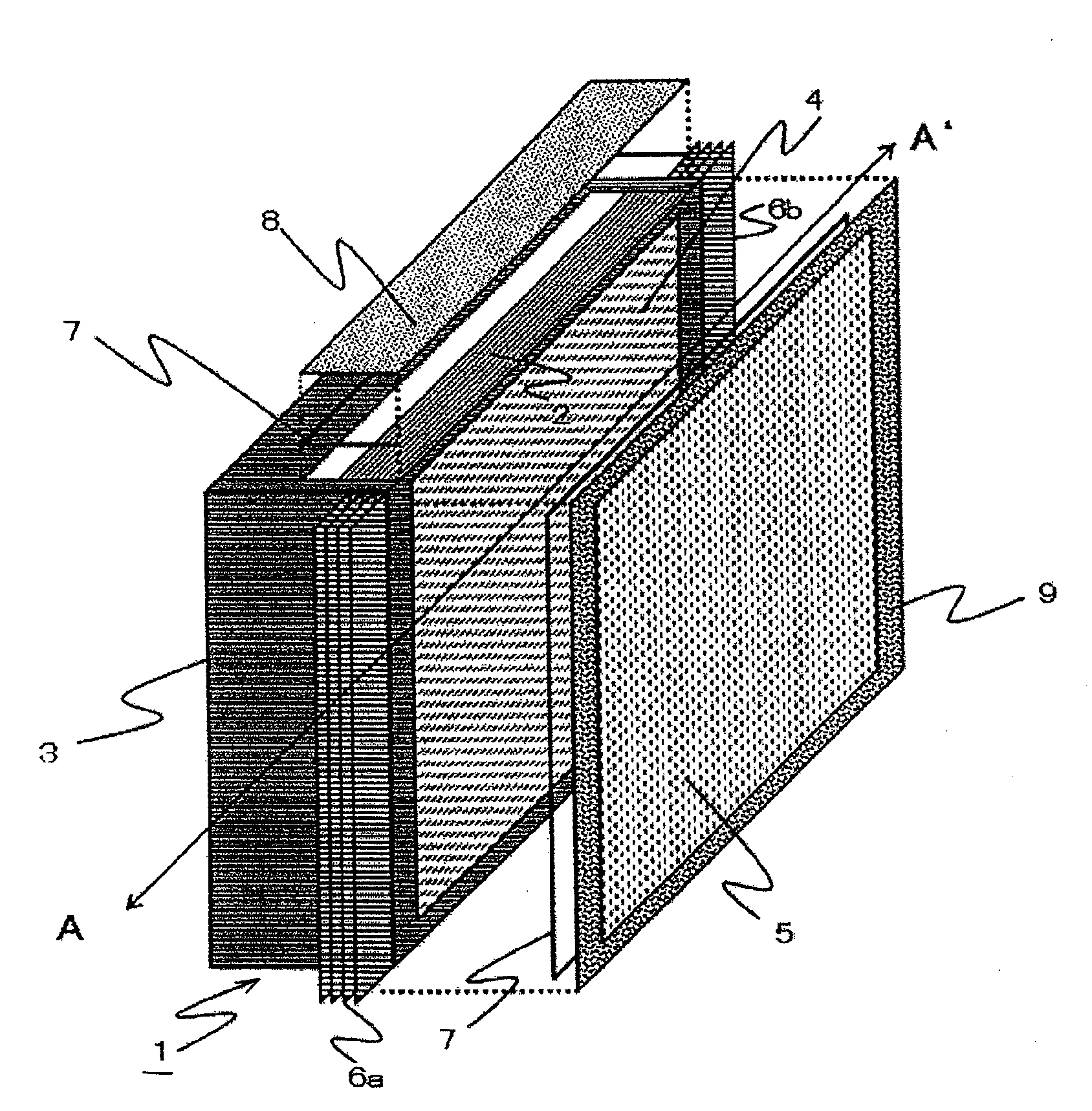
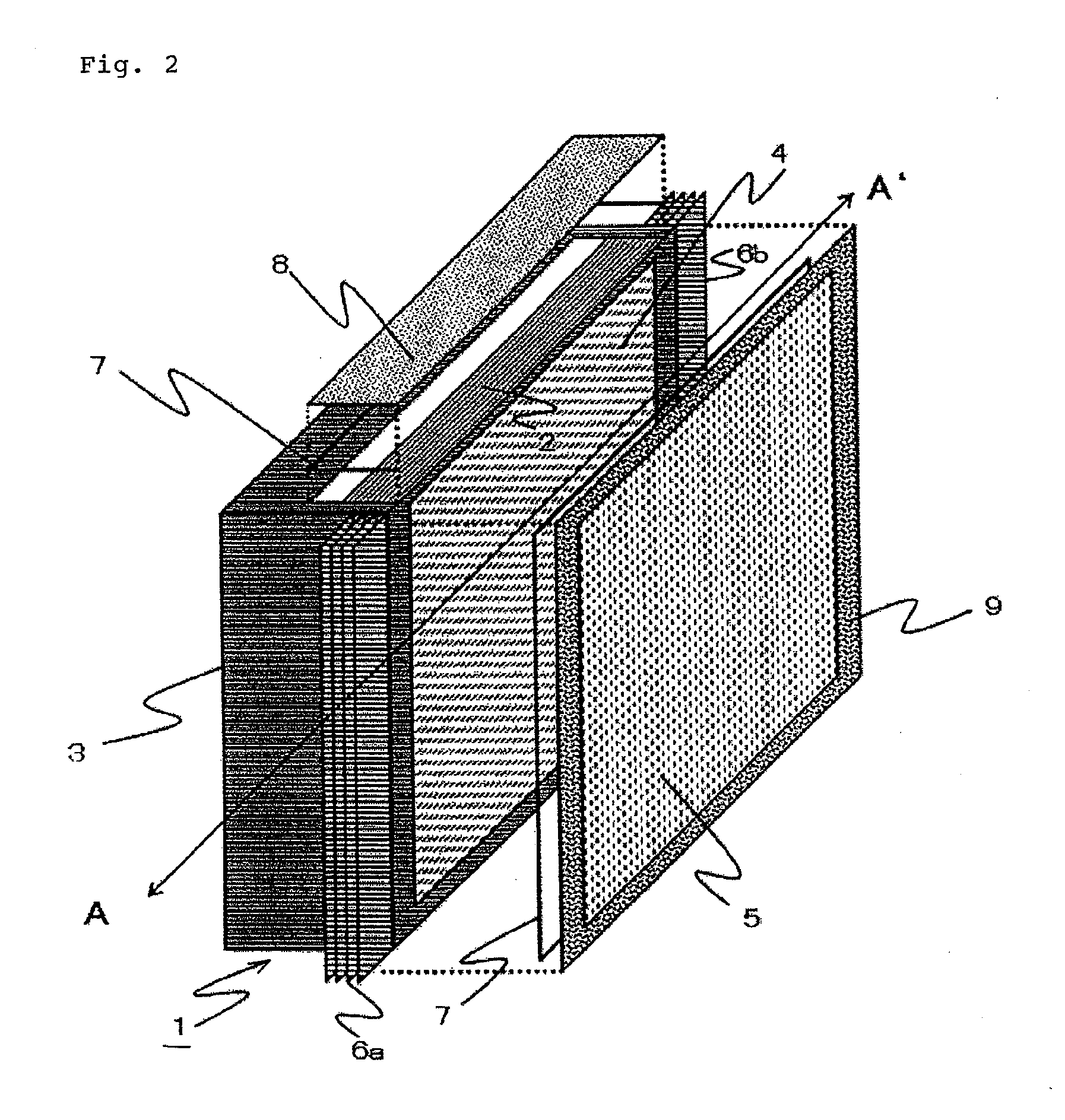
Provided is a highly reliable liquid crystal display device that prevents the penetration of a flying dust and dirt in the outside air. A liquid crystal display device (1) having a display unit housing case (2) configured to house a light source unit and a display unit, and an electronic component housing case (3) configured to house an electronic component. The liquid crystal display device (1) is tightly closed and externally disposed with heat radiation fins (6a and 6b).

Description

TECHNICAL FIELD[0001]The present invention relates to a large-sized liquid crystal display device installed in semi-outdoor public facilities such as station platforms, and more particularly to a cooling means in a closed liquid crystal display device for preventing the penetration of dust and dirt flying in the outside air.BACKGROUND ART[0002]In recent years, the size and image quality of industrial-use liquid crystal display devices are increasing. The market of digital signage is expanding, the digital signage that displays useful information in diverse public facilities such as displaying services and seat availabilities at stations, airports, etc. or displaying information in shopping arcades, schools, and companies, and demands for large-sized liquid crystal display devices are expanding.[0003]In the background art as described above, for semi-outdoor instillation conditions in station platforms or the like in particular, damage to the surfaces of liquid crystal panels can be ...

Claims


Application Information

Patent Timeline
IPC IPC(8): G02F1/1335
CPCG02F1/133308H05K7/20972G02F1/133604G02F2001/133311G02F2001/133317G02F2001/133328G02F2001/133628G02F2201/36G02F2201/46G02F2201/50G02F2203/60G06F1/1601G06F1/20H05K7/20963G02F1/133385G02F1/133317G02F1/133311G02F1/133328G02F1/133628
Inventor MIKUBO, KAZUYUKIHASHIGUCHI, TAKEYASAKAMOTO, HITOSHI
Owner NEC CORP
Why Eureka
Eureka Blog
Learn More