
Multiple transmission apparatus with reduced coupling

a multi-transmission apparatus and coupling technology, applied in the field of multi-transmission apparatuses, can solve the problems of insufficient power efficiency of the cartesian transmitter, inability to meet the requirements of the error vector magnitude (evm) and the adjacent coupled power ration (acpr), and achieve the effect of reducing the impact of division or multiplication on the modulation index

Inactive Publication Date: 2011-05-19
KONINKLIJKE PHILIPS ELECTRONICS NV
View PDF15 Cites 5 Cited by
  • Summary
  • Abstract
  • Description
  • Claims
  • Application Information

AI Technical Summary

Benefits of technology

The present invention provides an improved multi-Tx / Rx system with reduced oscillator coupling. This is achieved by operating oscillator circuits at different frequencies, which reduces the possibility of coupling between them. The system includes a transmission apparatus and a method for generating transmission signals. The generated signals can be used in a receiver part of the system as a local oscillator signal. A corrector unit can also be provided to correct modulation data. The technical effects of the invention include reduced crosstalk issues, improved performance, and reduced impacts of division or multiplication on the modulation index.

Problems solved by technology

However, the Cartesian transmitter suffers from the disadvantage that is not the most power efficient architecture.
When these two oscillators are integrated on the same silicon die, coupling between the two oscillators will be present, and may cause huge problems.
Consequently, requirements concerning error vector magnitude (EVM) and adjacent coupled power ration (ACPR) may not be reached.

Method used


Image

  • Multiple transmission apparatus with reduced coupling
  • Multiple transmission apparatus with reduced coupling
  • Multiple transmission apparatus with reduced coupling

Examples


Embodiment Construction

[0020]In the following, a preferred embodiment will be described based on dual Tx polar transmitter architecture, which embodiment can be implemented in a MIMO system or a LINC (Linear amplification with Non-linear Components) system.

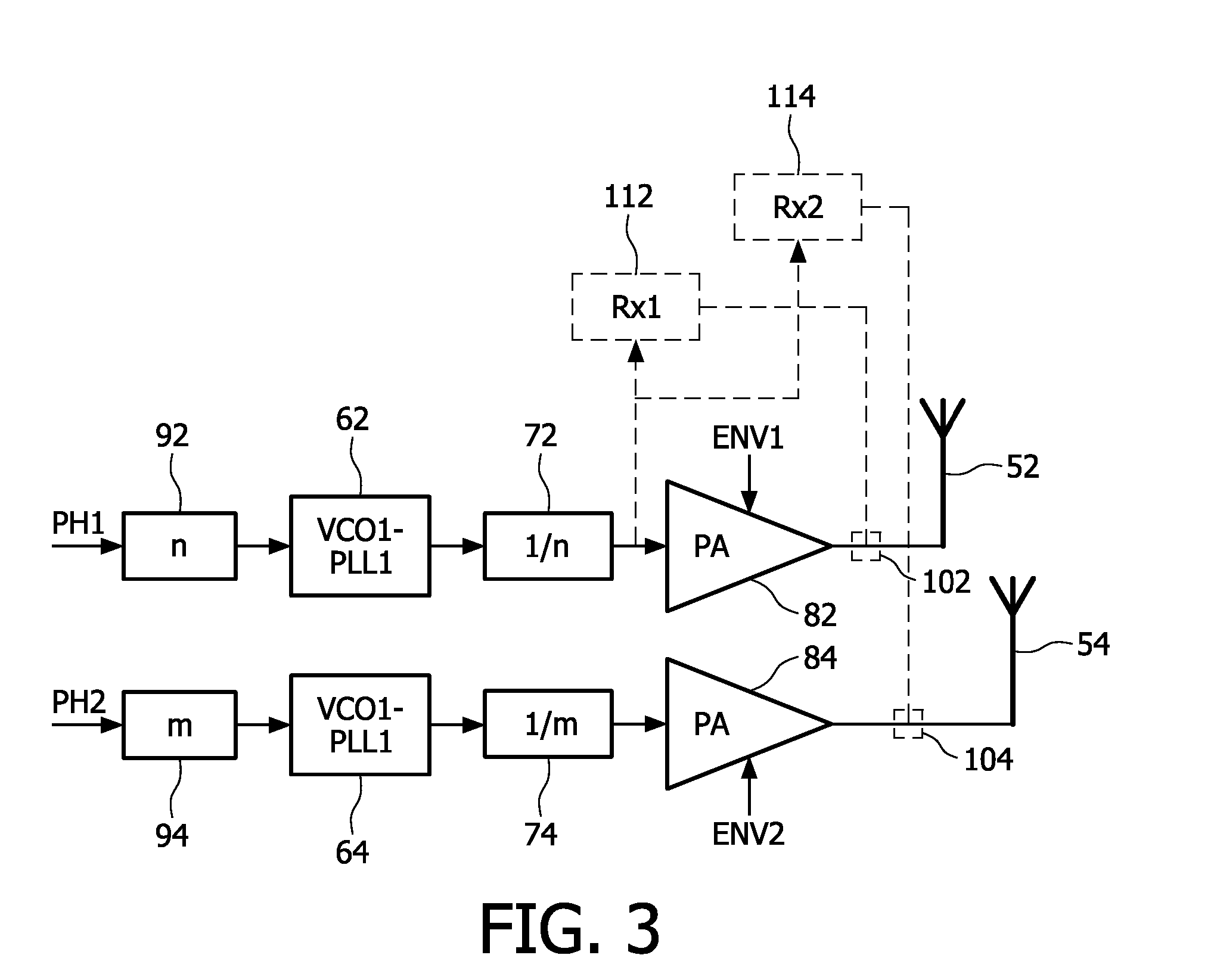
[0021]FIG. 3 shows a schematic block diagram of a polar transmitter architecture according to the preferred embodiment.

[0022]Different frequencies are used for VCOs / PLLs 62, 64 in each polar transmitter path, branch, or chain, thus minimizing the possibility for coupling between the multiple VCOs / PLLs. At the same time a solution is presented for using the best solution for a dual-receiver which may also be required in transceiver systems (e.g. MIMO) comprising both transmitter and receiver parts.

[0023]In the upper path, branch, or chain of FIG. 3, PH1-data denotes the phase information of a first polar transmitter. It is passed through a first correction stage 92 and used as modulation input for a first controllable oscillator circuit (e.g. VCO1 / PLL1) ...


PUM


Abstract

The present invention relates to a transmission apparatus having at least two transmission branches for transmitting respective transmission signals at substantially same frequencies, and to a method of controlling such a transmission apparatus. A first oscillator circuit (62) is provided for generating a first signal at a first frequency to be used in a first transmission branch. Additionally, a second oscillator circuit (64) is provided for generating a second signal at a second frequency to be used in a second transmission branch, the second frequency being different from the first frequency. To enable transmission of the transmission signals at said substantially same frequencies, at least one frequency divider or multiplier (72, 74) is provided for dividing or respectively multiplying at least one of said first and second frequencies by a respective predetermined factor. Thereby, the first and second oscillator circuits can be operated at different frequencies, so that mutual coupling can be reduced.

Description

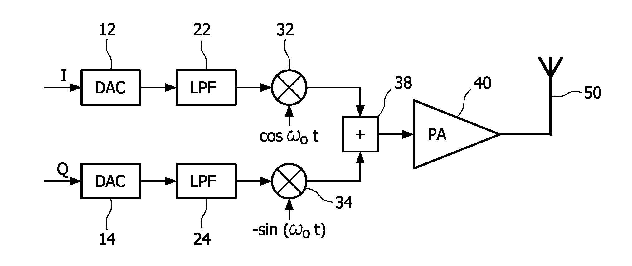
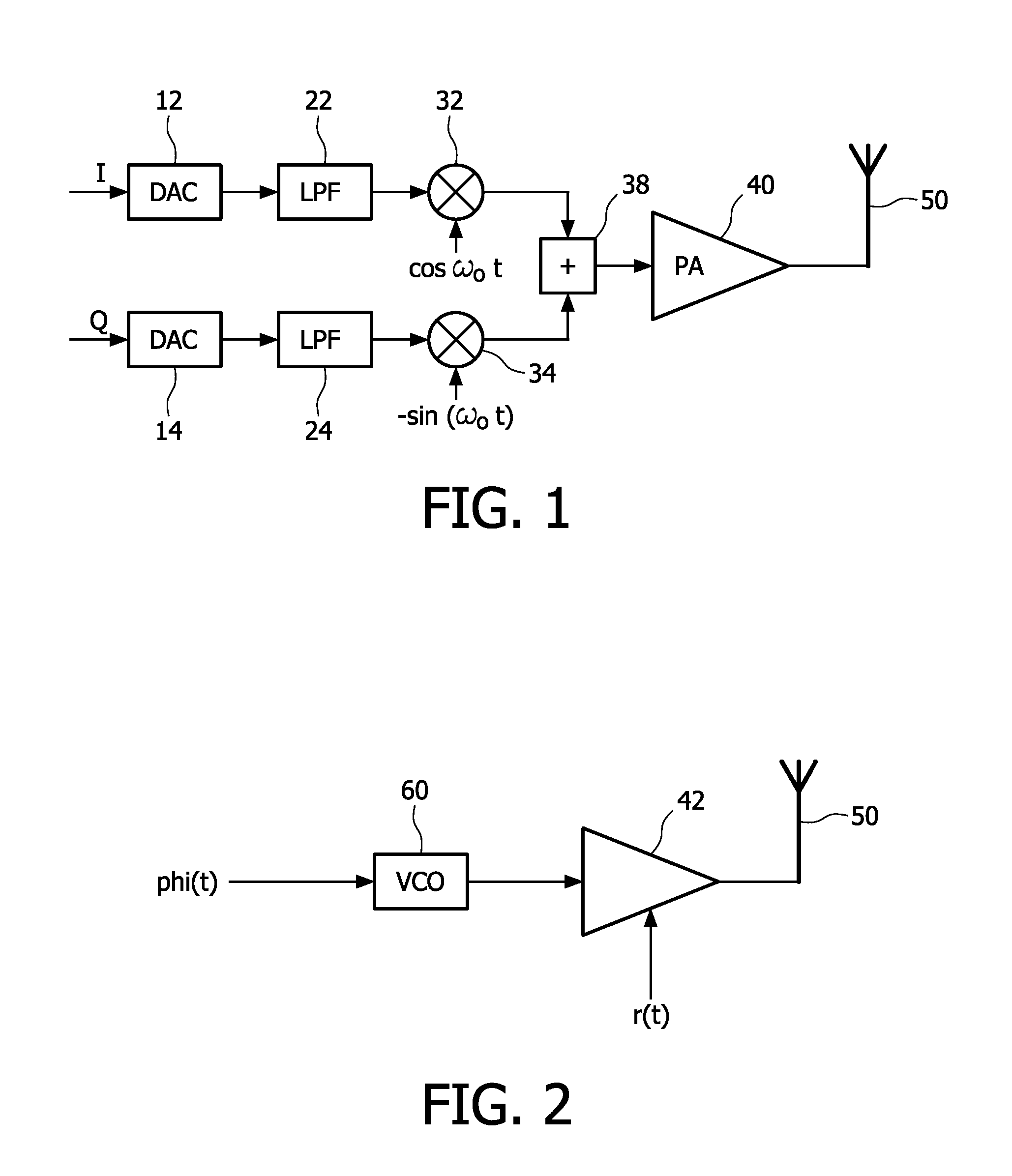
FIELD OF THE INVENTION[0001]The present invention relates to a transmission apparatus, such as a multiple input multiple output (MIMO) transmitter, receiver or transceiver, having at least two transmission branches for transmitting respective transmission signals at substantially same frequencies.BACKGROUND OF THE INVENTION[0002]Multiple transmit (Tx) and multiple receive (Rx) systems have received considerable attention in recent years as they offer substantial capacity improvements over conventional single-input single-output (SISO) systems. They have been proposed to achieve higher data rates, e.g. in wireless communication systems, with no penalty in either power or bandwidth. Multiple transmit (Tx) and multiple receive (Rx) antenna systems are referred to as multiple input multiple output (MIMO) systems.[0003]FIG. 1 shows a schematic block diagram of a conventional Cartesian transmitter device, wherein digital I- and Q-data output by a digital processing unit or the like are di...

Claims


Application Information

Patent Timeline
Patent Type & Authority Applications(United States)
IPC IPC(8): H04L27/00
CPCH04B1/0483H04B1/0475
Inventor VAN ZEIJL, PAULUS THOMAS MARIADUPERRAY, DAVID BENOIT DIDIERCOLLADOS ASENSIO, MANEL
Owner KONINKLIJKE PHILIPS ELECTRONICS NV
Learn More