Reflective optical transmitter

a technology of optical transmitters and optical fibers, applied in electromagnetic transmitters, fiber transmission, electromagnetic transmission, etc., can solve the problems of unnecessary additional cost to the device, complex design, and inability to achieve any benefit, and achieve the effect of suppressing intensity and interferometric nois

Inactive Publication Date: 2011-05-19
UNIV COLLEGE CORK NAT UNIV OF IRELAND CORK
View PDF2 Cites 4 Cited by
  • Summary
  • Abstract
  • Description
  • Claims
  • Application Information

AI Technical Summary

Benefits of technology

[0032]In one embodiment, the attenuation control is such that the optical amplifier, operated in a highly saturated regime, suppresses intensity and interferometric noise present in the optical carrier.

Problems solved by technology

The prior view of the approach of the invention would have been that one is “wasting” some of the amplifier gain by adding extra loss, thereby complicating the design and adding unnecessary additional cost to the device, and not achieving any benefit.

Method used


Image

  • Reflective optical transmitter
  • Reflective optical transmitter
  • Reflective optical transmitter

Examples


Embodiment Construction

Brief Description of the Drawings

[0034]The invention will be more clearly understood from the following description of some embodiments thereof given by way of example only with reference to the accompanying drawings, in which:

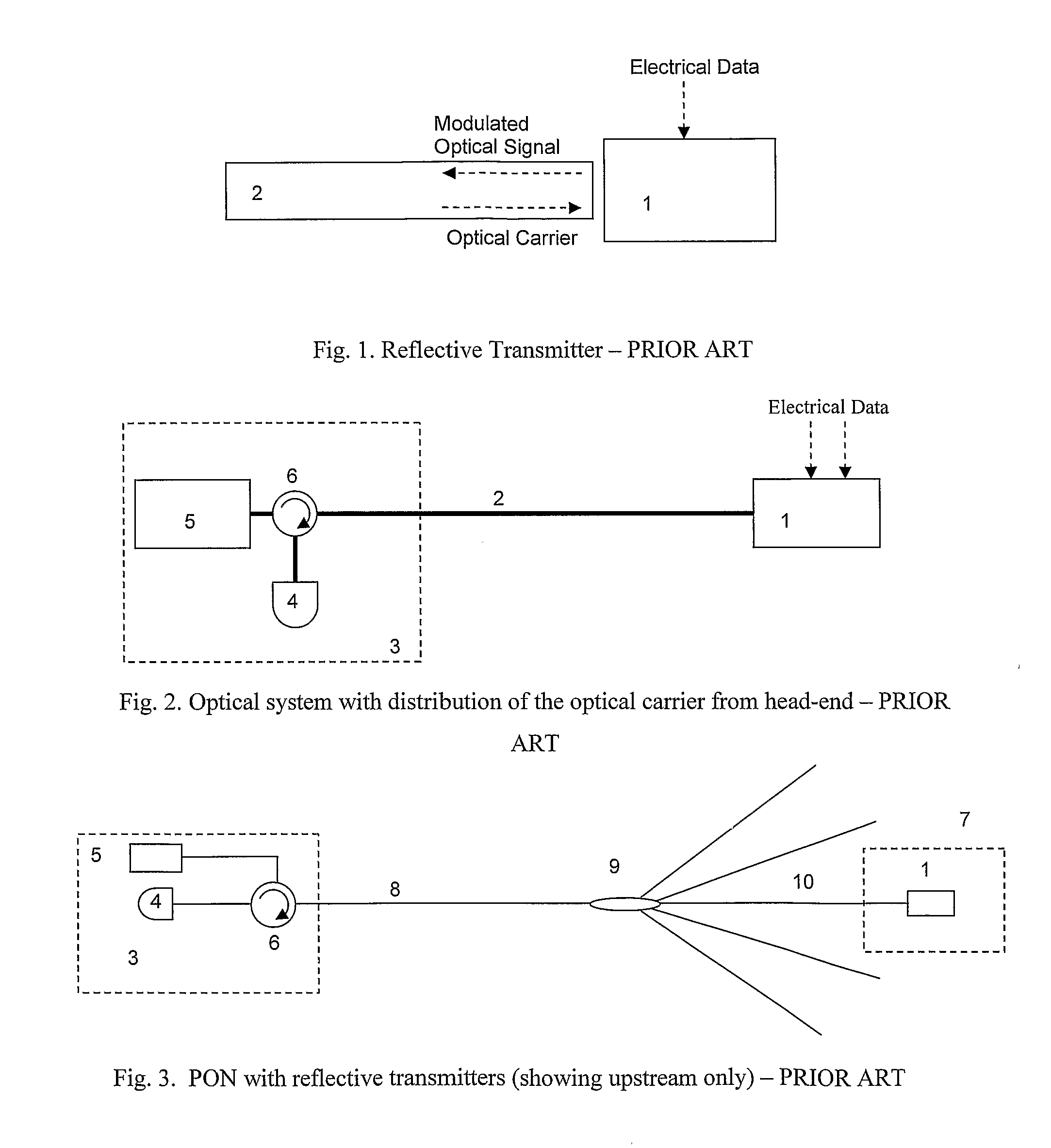
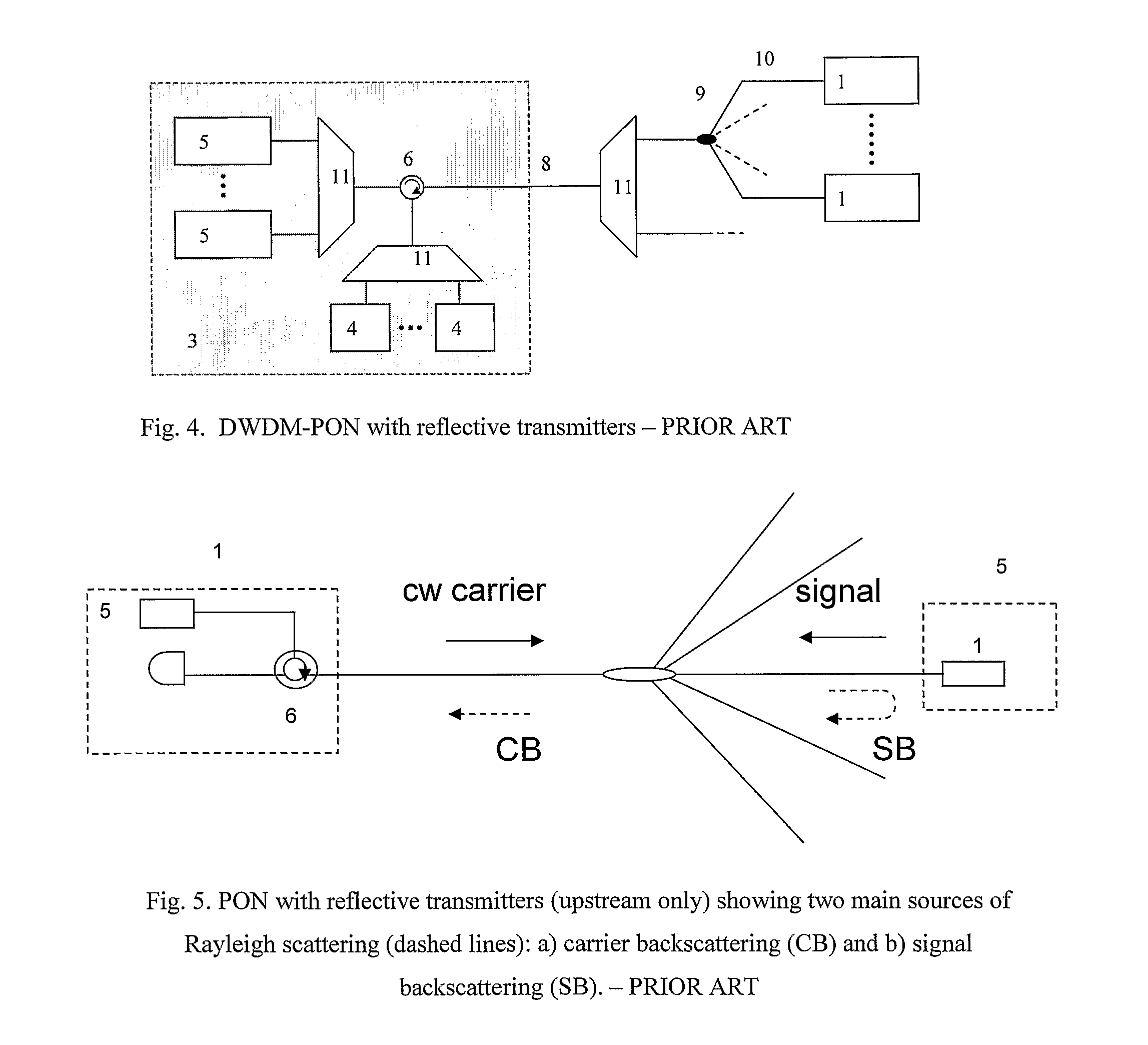
[0035]FIGS. 1 to 5 are diagrams concerning the prior art, as set out above;

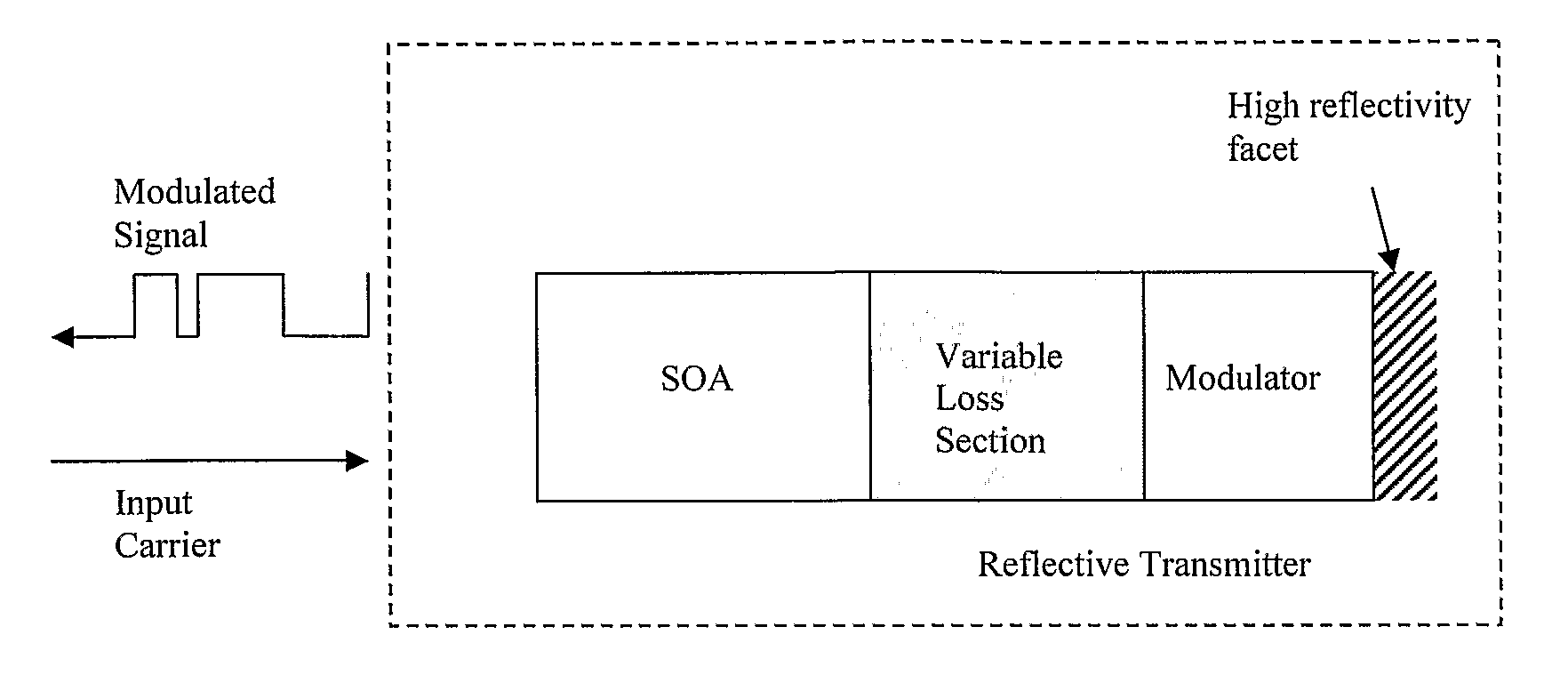
[0036]FIG. 6 is a diagram showing schematically the structure and internal components of an optical transmitter of the invention;

[0037]FIG. 7 is a diagram showing the carrier and modulated signal propagating through the various sections of the transmitter;

[0038]FIG. 8 is a plot showing simulation results demonstrating advantage of the invention concerning the reduction of the output signal dynamic range compared to the input carrier dynamic range;

[0039]FIGS. 9 to 11 are plots showing simulation results demonstrating advantages of the invention concerning the reduction of intensity and interferometric noise and the reduction of the distortion of the output signal; and

[0040]FIGS. 12 to 15...


PUM


Abstract

A semiconductor optical amplifier (SOA) is used in a double pass configuration with one of the output ports followed by an attenuator, which is followed by a modulator with a reflective facet. The variable loss between the SOA and the modulator is optimised, so that the SOA can be operated in a highly saturated regime without distorting the modulated signal. The SOA is firstly saturated by the input carrier, (21) in FIG. 2, which has a constant power and hence does not introduce patterning of the SOA gain. On the contrary the saturation induced by the carrier creates a clamping effect that prevents patterning for signals with input put power comparable with or less than the input optical carrier power. The optical carrier amplified by the SOA (22) then travels through the attenuator section and it is attenuated (23). The carrier (23) then enters the modulator section where it is modulated with the data signal (24). After being reflected by the high reflectivity facet the modulated signal (25) propagates again through the modulator section. If the modulator section length is short compared to the modulation bit rate, the double passing increases the modulation depth or extinction ratio without introducing distortion. The modulated signal (26) travels a second time through the attenuator and then enters the SOA (27).

Description

INTRODUCTION[0001]1. Field of the Invention[0002]The invention relates to reflective optical transmitters that can be applied in optical communication networks such as passive optical networks (PONs).[0003]2. Prior Art Discussion[0004]FIG. 1 shows the basic operation of a reflective optical transmitter (1). An electrical data signal is modulated onto an optical carrier. The resulting modulated optical signal then exits the reflective transmitter in the opposite direction to the optical carrier. The optical carrier and modulated signal thus counter-propagate in the same transmission medium (2).[0005]An application of reflective transmitters is in optical communication systems, where both the optical carrier light source (i.e. the laser) and the receiver are at the head end and the transmitter station contains simply a reflective transmitter. FIG. 2 shows such a system, where (1) is the reflective transmitter in a remote location and (3) is the head-end of the communication system. Th...

Claims


Application Information

Patent Timeline
Patent Type & Authority Applications(United States)
IPC IPC(8): H04B10/04H04B10/2587
CPCH04B10/2587
Inventor TALLI, GIUSEPPETOWNSEND, PAULMACHALE, ELMEAR
Owner UNIV COLLEGE CORK NAT UNIV OF IRELAND CORK
Why Eureka
Try Eureka