Universal dental crown and system and method of restoring a tooth using a universal dental crown

Inactive Publication Date: 2011-05-19
TRI DENT INNOVATIONS
View PDF29 Cites 10 Cited by
  • Summary
  • Abstract
  • Description
  • Claims
  • Application Information

AI Technical Summary

Benefits of technology

It is an object of the present invention to provide dentists and their patients with an alternative type of dental crown / restoration that is strong, easily fitted in one appointment and costs less than the laboratory or CAD / CAM crown. The present inventive crown addresses these goals, amongst others.
The crown matrix further comprises a perforation or thinned portion to promote tight fit of the dental crown with an adjacent tooth or adjacent crown. A first perforation or thinned portion is disposed on the mesial surface of the crown matrix and enables tight fit of a mesial surface of the dental crown with a distal surface of an adjacent tooth or adjacent crown. A first perforation or thinned portion may also be disposed on the distal surface of the crown matrix and enables tight fit of a distal surface of the dental crown with a mesial surface of an adjacent tooth or adjacent crown.
The crown matrix sidewall further comprises at least a first perforation or vent disposed in the sidewall in the portion extending beyond the apical margin of the crown shell, the perforation or vent facilitating escape of excess amounts of a bonding and filling agent used to affix the dental crown to the prepared tooth.

Problems solved by technology

This process generates very accurate and successful crowns but the process is costly and requires at least two patient visits with a gap between, with sufficient time for the dental technician to complete the laboratory work.
These are ordinarily created directly in the mouth and are awkward for the dental professional to create and are more likely to fracture or otherwise fail.

Method used


Image

  • Universal dental crown and system and method of restoring a tooth using a universal dental crown
  • Universal dental crown and system and method of restoring a tooth using a universal dental crown
  • Universal dental crown and system and method of restoring a tooth using a universal dental crown

Examples


first embodiment

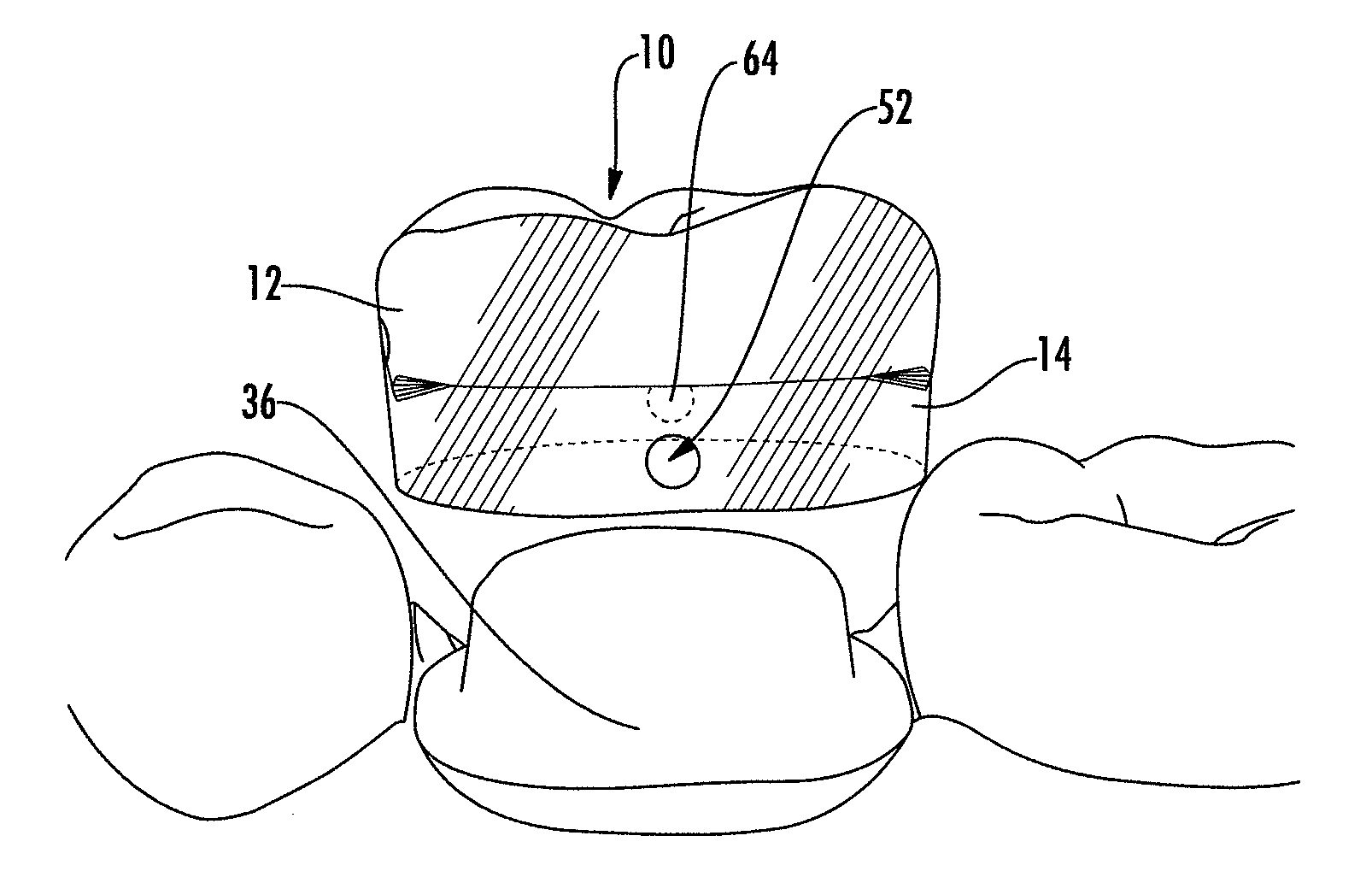
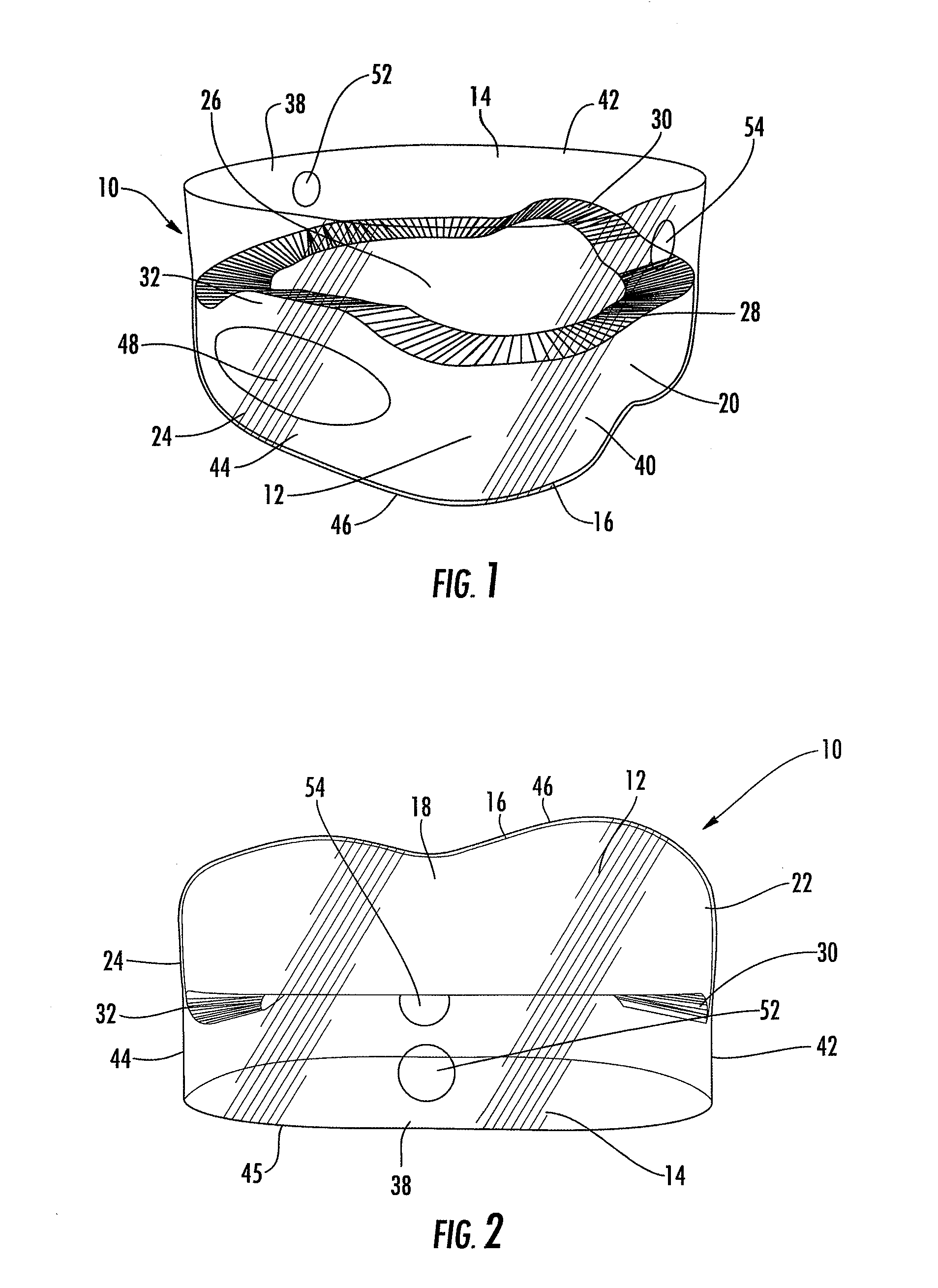
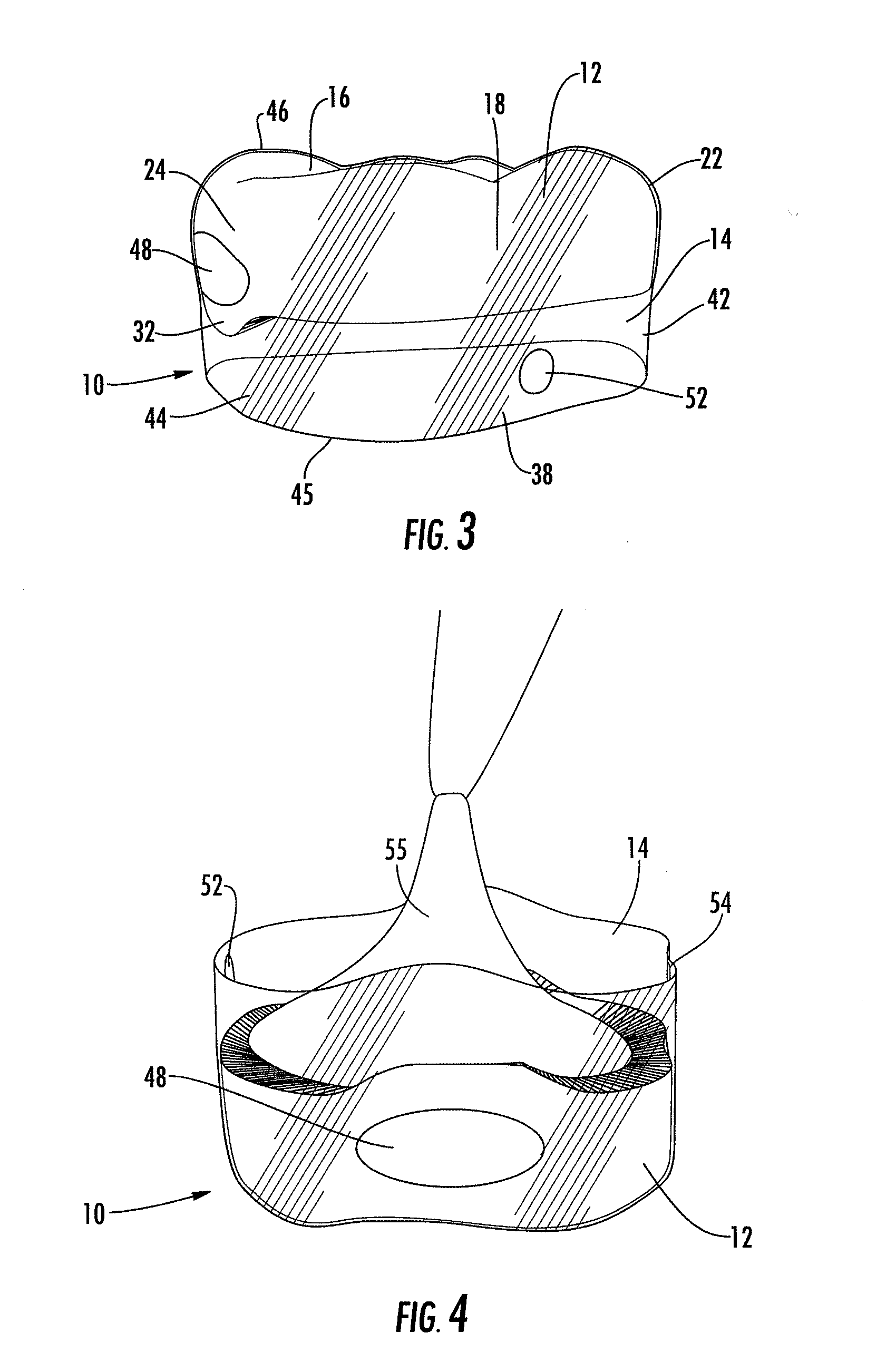
As shown in the attached figures, a dental crown 10 in accordance with the present invention comprises two primary components to form a single device. Referring specifically to the present invention shown in FIGS. 1-3, the dental crown 10 comprises a crown shell12 that is the inner component and a crown matrix 14 that is the outer component. The crown shell 12 is a universal component that is manufactured in a range of shades, tooth-types and sizes. The crown shell 12 is preferably composed of universal ceramic, metal, plastic or resin material formed using conventional means for working with these materials, such as plastic injection molding, pressing molten glass or injecting ceramic powders into molds and then consolidating the powders in a furnace. The crown shell 12 generally includes an occlusal surface 16 and side surfaces consisting of a buccal surface 18, lingual surface 20, distal surface 22, and mesial surface 24. FIG. 1 also shows an internal cavity 26 configured to rece...

second embodiment

FIGS. 7-9 show the present invention where the crown matrix 14 includes a hinged portion 56 enabling the occlusal surface 46 and portions of the buccal 38a, lingual 40a, distal 42a and mesial 44a surface to rotate about the hinged portion 56 exposing the internal cavity of the crown matrix 50. Whereas the sidewalls of the crown matrix 14 taper towards the gingival margin 45, rotating the crown matrix 14 about the hinged portion 56 into an open position will facilitate removal of the crown shell 12 from the crown matrix 14. Numbering used in identifying elements of the previously described preferred embodiments will be used to describe this preferred embodiment as well.

The buccal 38, lingual 40, distal 42 and mesial 44 surfaces of the crown matrix 14 are divided into upper and lower portions 38a,b, 40a,b, 42a,b, and 44a,b at margin 58. The margin 58 is a cut or separation that extends substantially around the circumference of the of the crown matrix 14, with the hinged portion 56 lef...

third embodiment

In the present invention shown in FIGS. 10-11, the crown matrix 14 includes a partial buccal 38, lingual 40, distal 42 and mesial 44 sidewall defining the internal cavity of the crown matrix 50 into which the crown shell 12 seats. The occlusal portion present in preferred embodiments discussed above is not present in this embodiment and is replaced by a first and second strap member 72, 74 that extends over the occlusal surface 16 of the crown shell 12. Whereas the sidewalls of the crown matrix 14 taper towards the gingival margin 45, limiting the height of the sidewalls to the margin 58 will facilitate removal of the crown shell 12 from the crown matrix 14 at the aperture defined by margin 58.

A first and second locking portion 60a, 60b are disposed at the ends of the straps 72, 74 and corresponding receptacles 62a, 62b are disposed on the buccal sidewall. In this preferred embodiment, the locking portions 60a, 60b are releasable, bobble-type cable ties. However, any suitable lockin...


PUM


Abstract

The present invention relates to dental crowns for use in restoring a prepared tooth wherein the dental crown comprises a universally sized crown shell and crown matrix to enable the sizing and fitting of the dental crown to the patient in a single sitting and without an impression or laboratory procedure.

Description

FIELD OF THE INVENTIONThe present invention relates to a universal dental crown and system that enables a dental professional to create and bond a dental crown in place without an impression or laboratory procedure.BACKGROUND OF THE INVENTIONTraditionally, porcelain or ceramic dental crowns have been made by a dental technician using a model of the tooth that was cast from an impression. This process generates very accurate and successful crowns but the process is costly and requires at least two patient visits with a gap between, with sufficient time for the dental technician to complete the laboratory work.More recently, a CAD / CAM process has been developed whereby digital data from a 3D scan of the tooth is imported into a CAD / CAM program and a ceramic crown is designed and milled from a block of material using a sophisticated CNC milling machine. The alternative to a porcelain or ceramic crown for a patient with limited financial means is a composite resin crown. These are ordin...

Claims


Application Information

Patent Timeline
IPC IPC(8): A61C5/11A61C5/10A61C5/77
CPCA61C5/08A61C5/70A61C13/0001A61C5/73
Inventor MCDONALD, SIMON PAULDOUDNEY, ADAM
Owner TRI DENT INNOVATIONS
Why Eureka
Try Eureka