LED illumination apparatus
a technology of led illumination and led wire, which is applied in the direction of lighting and heating apparatus, semiconductor devices for light sources, and connection of coupling devices, etc., and can solve the problems of difficult parts exchange, structurally difficult to remove, and not only difficult to work
- Summary
- Abstract
- Description
- Claims
- Application Information
AI Technical Summary
Benefits of technology
Problems solved by technology
Method used
Image
Examples
embodiment example 1
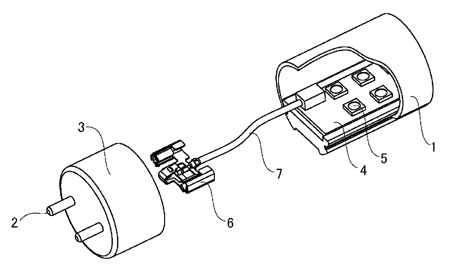
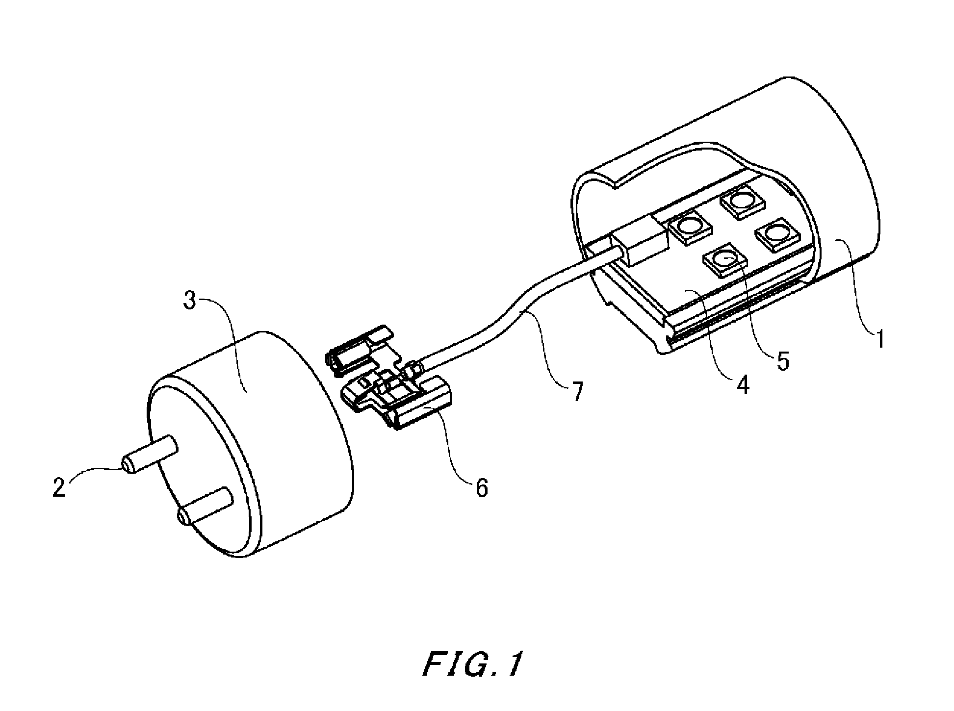
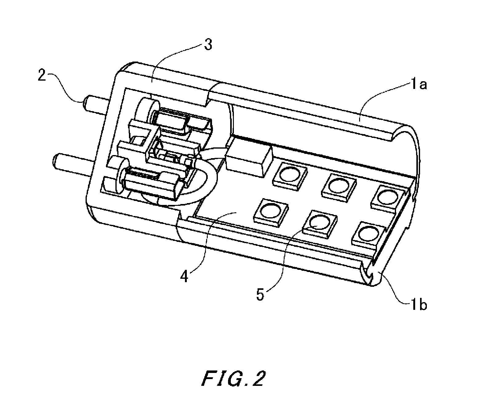
[0037]The main body 1 is a combination between an optical diffusion section 1a made of a transparent or semi-transparent resin (e.g. polycarbonate resin) and a heat dissipating section 1b made of an aluminum alloy or the like, and has a cylindrical form. However, the heat dissipating section 1b may be created as a heat sink having convex and concave portions. Note that the main body 1 is not limited to the described combination, and may be made of only a resin.
[0038]The cap 3 having a pair of pin terminals 2 made of a copper alloy sized to suit to an already installed fluorescent light fixture is joined to each end of the main body 1, and has a structure removable from the main body 1 for internal maintenance. Although FIG. 3 shows a cap 3 integrally formed with a pair of pin terminals 2 using an insulation resin, the pair of pin terminals 2 may be attached to the cap 3 by press fit or swaging. In addition, as shown in FIG. 4, a groove 3b for assembling the connecting terminal 6 and...
embodiment example 2
[0041]FIG. 8 shows a cap 3 and a connecting terminal 6 according to Embodiment Example 2. The only difference of the lock section 6c in Embodiment Example 2 from its counterpart in Embodiment Example 1 is that the lock section 6c in Embodiment Example 2 has a tongue-like shape. The lock section 6c is bent to be engaged with the lock engaging section 3a of the cap 3, thereby holding the connecting terminal 6. Note that the elasticity of the lock section 6c facilitates removal of the connecting terminal 6 from the cap 3 using a simple tool to cancel the lock. This also allows the cap 3 to hold the connecting terminal 6 with a simple structure, without using any additional parts.
embodiment example 3
[0042]FIG. 9 shows a cap 3 and a connecting terminal 6 according to Embodiment Example 3. The following explains only the differences from Embodiment Example 1. Each pin terminals 2 according to Embodiment Example 3 is provided with a groove 2a. A lock section 6d is formed on the connecting terminal 6. The lock section 6d is provided in the vicinity of the pin terminal connecting section 6b, so as to be engaged with the groove 2a, and holds the connecting terminal 6 by being engaged with the groove 2a by means of the elasticity of the lock section 6d. As shown in FIG. 10, by being provided with a protrusion 6d′, the lock section 6d is assuredly engaged with the groove 2a. Note that the elasticity of the lock section 6d facilitates removal of the connecting terminal 6 from the cap 3 using a simple tool to cancel the lock. In this way, according to the configuration of Embodiment Example 3, the cap 3 is not necessarily provided with a lock engaging section 3a, unlike in the case of Em...
PUM
 Abstract
Description
Claims
Application Information
 - R&D
- Intellectual Property
- Life Sciences
- Materials
- Tech Scout
- Unparalleled Data Quality
- Higher Quality Content
- 60% Fewer Hallucinations
Browse by: Latest US Patents, China's latest patents, Technical Efficacy Thesaurus, Application Domain, Technology Topic, Popular Technical Reports.
© 2025 PatSnap. All rights reserved.Legal|Privacy policy|Modern Slavery Act Transparency Statement|Sitemap|About US| Contact US: help@patsnap.com


